



Mechanical vs. Hydraulic Press: Stamping Line
 Aug 13, 2026|
 View:301
Mechanical Punch Press vs. Hydraulic Press: Which Is Right for Your Stamping Line?
Selecting the right equipment for metal stamping directly impacts operational efficiency. A high-speed mechanical press drives continuous, high-volume production of sheet metal blanking. A hydraulic press delivers precise force control for deep drawing, variable stroke depths, and heavy-gauge forming. Plant managers, manufacturing engineers, and procurement specialists must evaluate critical performance metrics to align equipment capabilities with specific manufacturing needs.
Key evaluation criteria include strokes per minute (SPM), tonnage curves across stroke length, energy efficiency, tooling wear, and coil material feeding compatibility. Choosing between a mechanical punch press and hydraulic alternative requires analyzing these operational factors. This technical comparison outlines the difference between the two drive technologies, the advantages and disadvantages of each, and the exact capabilities they offer modern metalworking facilities.
Key Takeaways
Mechanical presses run very fast and create high volumes of simple sheet metal parts.
Hydraulic presses supply full power through the entire stroke to shape thick metal parts.
Operators easily adjust hydraulic press speed and height using simple digital controls.
Hydraulic systems save electricity during pause times because their pumps can stop completely.
Integrated 3-in-1 coil systems flatten raw metal and feed it accurately into the machine.
Factory managers choose the best press by comparing part shapes and total production goals.
Mechanical Punch Press Working Principles
Flywheel Kinematics and Energy Transfer
Flywheel and Clutch Engagement
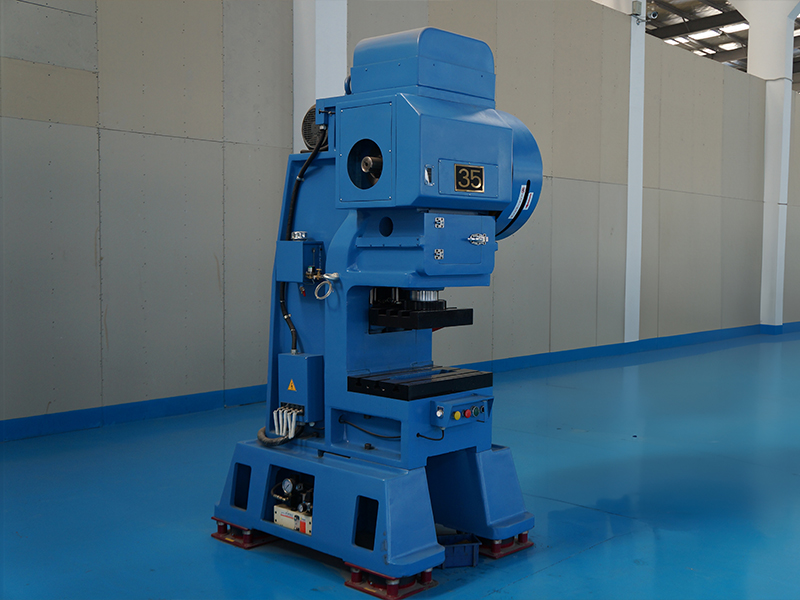
An electric motor supplies continuous rotational energy to a heavy flywheel. The flywheel stores this kinetic energy during non-stamping intervals. When the machine receives a stroke signal, the clutch engages the spinning flywheel to the main drive shaft. This action transfers rotational energy directly into the drive mechanism to initiate ram movement.
Mechanical punch presses rely heavily on this rapid energy transfer to maintain consistent cycling speeds. The clutch disengages automatically after completing a stroke, while a mechanical brake stops the drive shaft at top dead center. This quick engagement cycle enables high strokes per minute, which represents one of the main benefits of mechanical punch presses in modern manufacturing.
Crankshaft and Link Motion Mechanisms
The rotating drive shaft turns a crankshaft or an eccentric shaft inside the main frame. This rotation transforms continuous rotary motion into reciprocating linear motion through a connecting rod. The connecting rod drives the press ram up and down along vertical slide guides.
Link motion mechanisms modify this standard sinusoidal movement. Modified link designs slow the ram velocity down near the bottom of the stroke while preserving high transport speeds during the rest of the cycle. This kinematic control stabilizes blanking quality and extends tool life in every mechanical punch press installed on high-volume production lines.
Tonnage Delivery at Bottom Dead Center
Mechanical Advantage at Stroke Bottom
A mechanical press delivers force through physical linkage geometry rather than fluid pressure. The crank angle creates maximum mechanical advantage when the slide approaches the bottom of its travel. The system generates its full rated tonnage capacity only at or near bottom dead center.
The available force decreases sharply as the ram moves higher up the stroke path. Mechanical linkages cannot produce full working tonnage near the middle of the stroke.
A press rated at 200 tons may deliver only about 100 tons halfway through its stroke, indicating a 50% drop in available tonnage away from bottom dead center.
Fixed Stroke Tonnage Curves
The fixed mechanical connection establishes a non-adjustable stroke length. Engineers plot available force against ram position using fixed tonnage curves. Material thickness and die contact position determine the actual force available during a cutting or forming operation.
If the cut completes 15 mm above BDC (rated point at 6 mm), the available force is only 60-70% of nameplate tonnage, implying a drop of 30-40%.
This rigid force profile makes the mechanical punch press ideal for thin sheet metal blanking and shallow stamping operations.
Hydraulic Punch Presses: Force and Control
Fluid Dynamics and Cylinder Operation
Proportional Valve Regulation
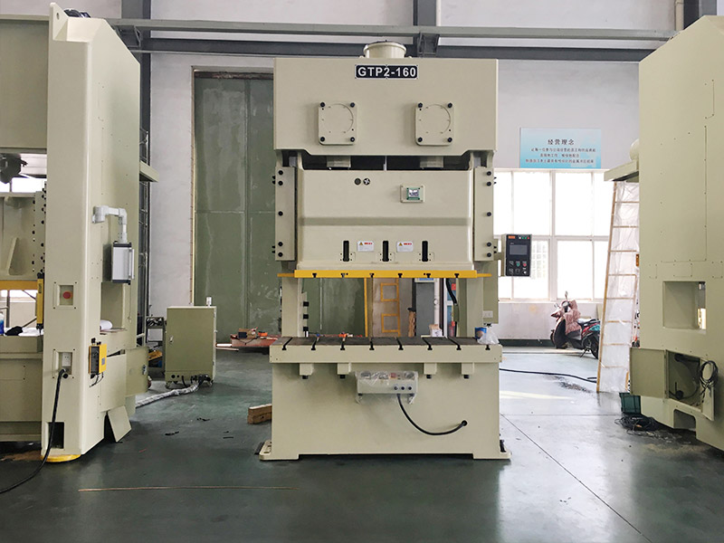
Positive displacement pumps deliver hydraulic fluid under pressure into heavy-duty cylinders to drive ram motion. Proportional valves regulate fluid volume and operating pressure throughout every stroke. This controlled fluid dynamics system replaces mechanical linkages with flexible fluid power.
Proportional valves dynamically adjust fluid flow to maintain continuous press accuracy during operation. Valve reaction time directly impacts system precision in hydraulic punch presses. Response times introduce another layer of error, typically ranging from 5 to 100 milliseconds depending on valve quality.
Hydraulic Ram Speed Profiles
Hydraulic fluid control allows operators to customize ram speed profiles across distinct cycle stages. Operators configure fast approach speeds, controlled pressing speeds, and rapid retract movements. This precise speed profile management prevents thermal stress on dies while maximizing part output.
Ram speed repeatability depends on the underlying drive mechanism:
Mechanical press: High repeatability due to fixed mechanical path.
Hydraulic press: Moderate repeatability, varies with oil temperature and valve performance.
Servo mechanical press: Ultra-high repeatability with micron-level electronic control.
Servo hydraulic press: Ultra-high repeatability with closed-loop sensor feedback, enabling precise ram speed control and dwell capability.
Constant Tonnage and Variable Stroke Control
Full Force Across Entire Stroke
Hydraulic punch presses provide maximum rated force at any position along the stroke travel. Unlike mechanical linkages, fluid pressure maintains full tonnage capacity right from initial material contact. This full-force output supports challenging heavy-duty pressing and deep drawing processes across thick metal stock.
Fluid control allows the machine to adjust instantly when processing raw material variations.
Hydraulic presses excel in precision. Pressure and position can be controlled tightly. Mechanical presses rely on fixed motion. They repeat well, but only within their design limits. If material thickness varies, mechanical presses struggle. Hydraulic presses adapt.
Programmable Dwell and Height Settings
Engineers easily adjust stroke length, open height, and reverse positions through digital controls. Remote hydraulic power units supply pressurized fluid to compact frame structures, optimizing floor space layout around the press. Flexible setup options rank high among the primary benefits of hydraulic punch presses in modern job shops.
Programmable dwell settings maintain full pressure at the bottom of the stroke to eliminate elastic springback in formed parts. This dwell capability ensures superior dimensional accuracy on difficult contours. These combined features deliver better forming and drawing capabilities across diverse sheet metal manufacturing operations.
Key Differences in Performance and Speed
Evaluating equipment options requires understanding key differences between drive technologies. Operational priorities often pivot around stroke velocity, dimensional accuracy, and floor space requirements. Mechanical drive systems excel in rapid cycling operations. Hydraulic drive systems offer deep control across variable working distances. Comparing these two mechanisms clarifies how speed profiles and frame structures impact overall plant productivity.
Operating Speed and Cycle Times
High SPM Flywheel Capabilities
Flywheel kinetic energy storage enables rapid slide movement during continuous production runs. A mechanical punch press cycles repeatedly without waiting for hydraulic fluid pressure build-up or valve adjustments. The rotating crank mechanism drives the ram through a fixed stroke path instantly. This rapid linkage movement provides high-speed capabilities that cut overall part processing times significantly.
Progressive die applications benefit immensely from uninterrupted flywheel rotation. Consistent drive speed ensures rapid material progression through multiple die stations. Manufacturers achieve higher production and efficiency on thin-gauge material runs by deploying specialized C-frame high-speed presses for continuous mechanical lines.
The AIDA PMX-3000 press, a 300-ton progressive die press, has a maximum stroke per minute (no load) of 100 spm, as indicated in the press technical data table.
Hydraulic Ram Speed Adjustability
Hydraulic systems utilize proportional valves to regulate fluid flow during ram travel. An operator programs distinct speed profiles for approach, pressing, and retraction phases within a single stroke. The ram accelerates quickly during fast approach mode, decelerates right before initial die contact, and maintains a controlled speed throughout the press stroke.
This multi-stage speed transition lengthens total cycle duration compared to crank-driven systems. Hydraulic punch presses cannot match the sheer production speed of mechanical systems due to fluid response intervals. However, variable ram speed prevents severe thermal stress on dies and reduces material fracture during deep draw forming, which is what the forming requirements of deep-drawn parts demand. The controlled fluid movement delivers exceptional flexibility across complex metal shaping tasks.
Precision, Ram Control, and Footprint
Frame Deflection and Parallelism
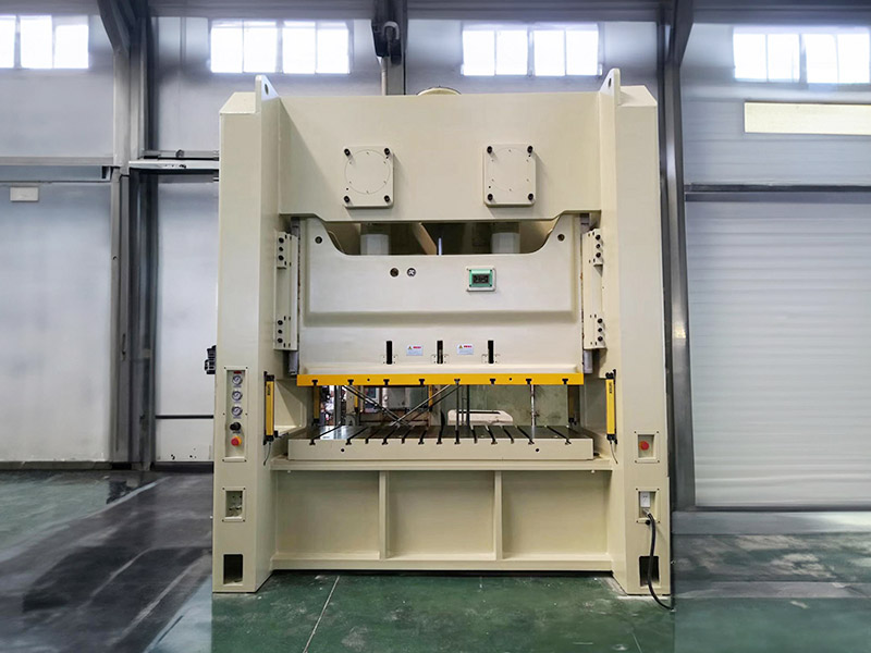
Maintaining strict slide parallelism under heavy working loads directly protects die tooling. Off-center loading creates frame deflection when high tonnage concentrates away from the bed center. A mechanical press relies on rigid frame structures—such as robust double-crank H-frame presses—and precision gib alignment to resist twisting forces under eccentric load conditions.
Hydraulic systems manage off-center loading through dynamic valve adjustments across multiple drive cylinders. Closed-loop controls adjust pressure across individual fluid circuits to maintain ram parallelism during complex blanking or forming operations. Fixed mechanical links deliver high slide position repeatability at bottom dead center. Conversely, fluid systems adjust ram pressure dynamically to preserve part quality across varying material yield strengths.
Equipment Footprint and Power Layouts
Physical machine dimensions play an important role in manufacturing plant floor planning. A standard mechanical press features a tall vertical profile due to top-mounted flywheels, crown gear drives, and heavy crankshaft housings. High ceiling clearance is necessary to accommodate these overhead components during installation and routine service.
Press Attribute | Mechanical Press System | Hydraulic Press System |
|---|---|---|
Drive Structure Location | Top-mounted flywheel and drive shaft | Remote power unit or bed-mounted cylinders |
Vertical Clearance Requirement | High clearance required for crown assembly | Compact frame design with lower ceiling height |
Power Distribution | Direct mechanical linkage and clutch | Flexible hydraulic hose lines and manifold blocks |
Another point highlights key differences in power layout configuration. Hydraulic power units can stand adjacent to the main press frame or inside remote utility rooms. This modular hydraulic layout optimizes working space around primary stamping zones. Compact frame designs simplify crane access and speed up material handling access across busy production floors.
Material Feeding and Stamping Line Integration
Press selection directly dictates the coil feeding automation requirements for a production line. A mechanical press demands rapid material delivery to match continuous high-speed strokes. Conversely, hydraulic units require feeding systems that pause during longer dwell periods and variable stroke profiles. Stamping operations must integrate compatible coil handling equipment to eliminate material stress, curvature, and positioning errors before stock reaches the die.
Mechanical Punch Presses vs Hydraulic Systems Feeding Needs
High-Speed Continuous Feeding Requirements
Continuous operations using a mechanical press require ultra-fast coil feed cycles. The feeding system must advance raw sheet metal in milliseconds during the short interval between ram strokes. Insufficient feed speed creates misfeeds, jams, or severe die damage during rapid blanking.
Automation equipment must synchronize perfectly with crankshaft rotation signals. High-speed electronic feeders continuously deliver stock without stopping flywheel movement. This precise alignment preserves maximum throughput across high-volume production lines.
Deep Draw and Variable Dwell Feeding Synchronization
Hydraulic presses require a flexible material feeding pace. The hydraulic ram often stops at the bottom of a stroke to perform deep drawing or variable dwell forming. The material feeder must remain stationary during this extended dwell period to prevent binding.
Variable cycle times require adaptable control signals between the press and feeder. Automated systems wait for hydraulic ram retraction before advancing the next coil section. This dynamic timing prevents material tear and die misalignment on complex forming cycles.
Integrating Automated 3-in-1 Coil Processing Systems
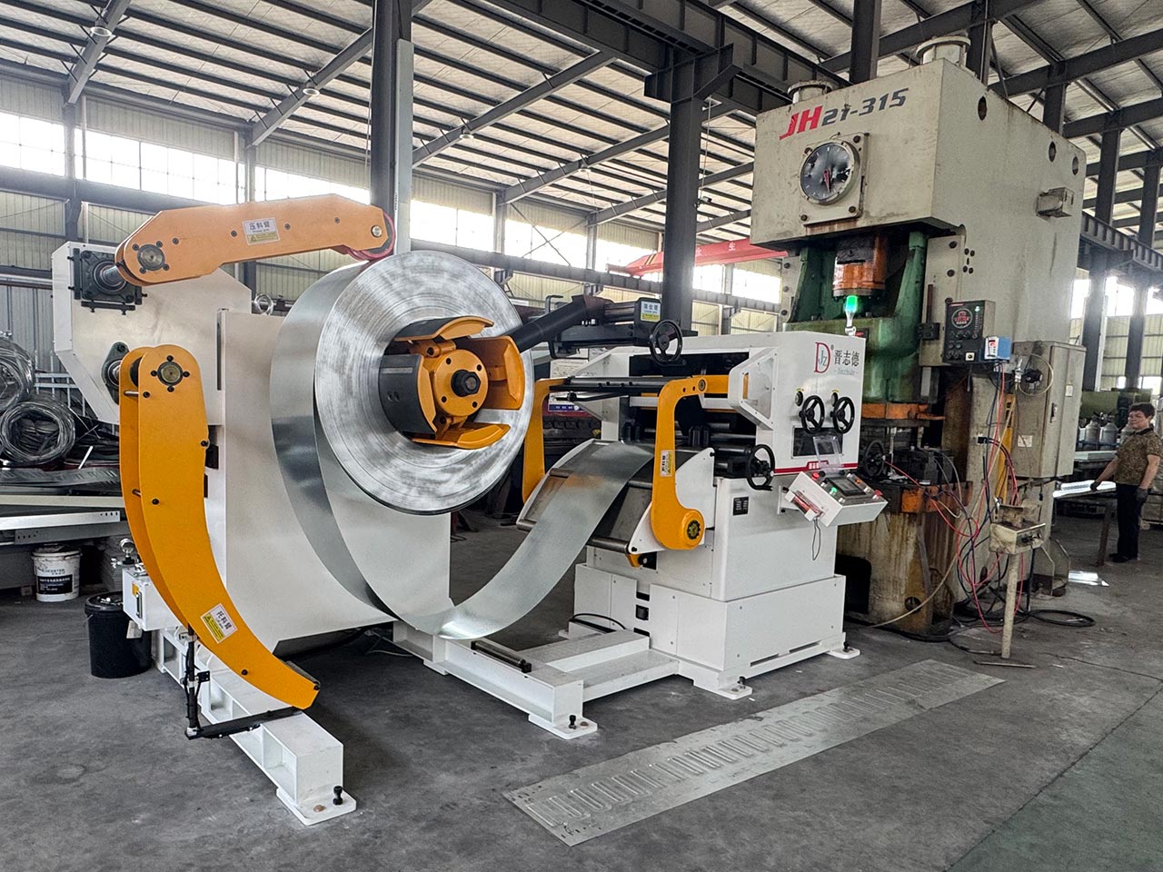
JINZHIDE Decoiler Straightener Feeder Setup
The JINZHIDE Decoiler Straightener Feeder combines uncoiling, precision leveling, and high-accuracy servo feeding into one 3-in-1 integrated coil processing system. Built under strict ISO9001 quality standards, this machine prepares metal coils for metal stamping applications.
The straightening section uses precision-machined rollers in alternating positions to flex the strip repeatedly, removing internal stress and restoring flatness. Proper leveling improves die contact, reduces spring-back, and enhances bending quality across various metal working setups.
The straightening amount directly impacts material flatness. Set the opening gap between upper and lower rollers at the inlet end slightly less than at the outlet end. Adjust while running the servo motor forward and reverse in manual mode until the material exits flat.
Floor Space Optimization and Feeding Accuracy
The JINZHIDE Decoiler Straightener Feeder optimizes factory floor space by combining three separate machines into a compact footprint. This unit simplifies coil loading, enhances operator safety, and reduces overall setup times.
The system synchronizes seamlessly with high-speed press feeds and heavy-duty hydraulic press setups up to 2000 tons. Its servo-driven feed rollers maintain high dimensional consistency across every stroke.
Improved part appearance due to stress-free material preparation.
Consistent feeding accuracy of ±0.1 mm for progressive die applications.
Adjustable feed roller pressure to prevent surface marking or strip slippage.
Operational Costs, Maintenance, and Tooling
Plant operators must calculate total operational costs across electrical consumption, routine machine maintenance, and precision die servicing. Drive architecture directly dictates long-term power demands and component longevity. Evaluating these financial variables ensures proper equipment selection for modern manufacturing environments.
Energy Efficiency and Power Draw
Kinetic Energy Storage Consumption
An electric motor runs continuously to keep the heavy flywheel spinning on a mechanical press. This continuous flywheel rotation consumes electrical energy even when the machine sits idle between individual stamping strokes. The drive system draws energy continuously from the facility power grid to maintain rotational velocity.
Idle energy draw increases utility costs during die adjustments, stock changes, or coil reloading pauses. High-speed kinetic energy storage yields high operating efficiency during uninterrupted high-volume blanking runs. However, frequent production stops make continuous flywheel rotation less economical for facilities with varied short-run production schedules.
Demand-Based Hydraulic Power Units
Hydraulic systems utilize positive displacement fluid pumps to pressurize hydraulic oil strictly during active ram movement. Modern hydraulic power units feature digital control valves and variable frequency drives that dynamically adjust electric motor speeds based on immediate press tonnage demand.
This dynamic power regulation delivers a lower idle power cost during long tool setup periods and manual part loading cycles. The main pump decelerates or pauses entirely when the ram remains stationary at top dead center. A direct cost comparison reveals that demand-based hydraulic power units cut total electricity consumption during low-duty or intermittent production schedules.
Maintenance and Tooling Longevity
Mechanical Component Wear Points
Mechanical drive linkages rely on heavy friction clutches, mechanical brake shoes, drive straps, and precision crankshaft bearings. Continuous high-speed engagement causes steady mechanical wear across internal contact surfaces, which increases overall replacement costs over extended operating hours. Severe operational environments accelerate mechanical fatigue in heavy drive components.
Maintenance teams must inspect brake linings, clutch plates, and automated central lubrication systems regularly to prevent catastrophic component failure. Proper lubrication protocols help lower repair cost across high-use production lines. Nevertheless, friction components experience unavoidable degradation and require complete mechanical replacement over time.
Tooling Wear and Overload Protection
High-speed sheet metal blanking creates severe snap-through shock when raw material fractures instantly under tension. This sudden release of stored mechanical strain energy transmits heavy reverse impact forces backward into the press slide and die tooling. Violent reverse shock waves accelerate cutting edge chipping, driving up tooling maintenance costs over time.
Hydraulic pressure relief valves safeguard precision tooling against unexpected tonnage spikes and severe die jamming during complex forming operations. Built-in hydraulic overload limiters absorb sudden reverse shock loads gracefully during breakthrough. Controlled fluid displacement reduces tool repair cost and extends overall die life, offsetting long-term operational costs across demanding metalworking applications.
Which Press Is Right for Your Stamping Line?
Selecting the best press technology requires a thorough evaluation of your facility targets. Plant managers must analyze specific component designs alongside long-term production goals. Operating requirements determine which press is right for a specific factory floor. Matching drive mechanics to your exact application prevents costly manufacturing bottlenecks and optimizes operational output across every shift. Modern manufacturing plants must balance equipment investment costs with daily processing speeds to remain competitive.
Application Suitability Breakdown
Understanding application needs helps engineering teams select between mechanical linkages and fluid power drives. Each system provides distinct operational advantages based on part geometry, material behavior, and output expectations.
High-Volume Blanking and Piercing
High-volume manufacturing lines demand extreme operational speed and fast cycling times. Flat sheet metal parts require rapid cutting, piercing, and shallow shearing across continuous runs. A mechanical punch press delivers the continuous mechanical force needed for these fast operations. Flywheel energy storage drives continuous stroke movement without operational pauses or speed variations. The kinetic energy conversion delivers peak force right at bottom dead center during every cycle.
Facilities producing high-volume electrical components, washer components, and hardware fasteners rely on continuous mechanical drive lines. Operations exceeding 10,000 units benefit significantly from continuous mechanical cycling. Mechanical drive systems maintain rapid cycle rates between 60 and 1,500+ strokes per minute. These impressive speed ranges lower piece costs across massive production runs. Thin sheet stock moves through progressive dies continuously to maximize hourly output. Simple geometries with low to medium complexity benefit most from this reliable mechanical design.
Deep Drawing and Complex Forming
Complex part shapes demand extended fluid pressure during deformation. Heavy structural automotive panels, deep enclosures, and complex industrial housings require precise ram control. A hydraulic press delivers continuous full force throughout the entire working stroke length. Fluid pressure ensures uniform material flow without cracking or thinning sheet stock. The ability to control ram deceleration near material contact reduces stress on sensitive workpiece regions.
Low to medium production volumes with high part complexity fit hydraulic drive systems best. Variable cycle speeds between 10 and 30 strokes per minute allow deep plastic deformation. The extended contact time prevents structural defects in high-tensile material stock. Fluid power systems accommodate quick die changes, making them optimal for high-mix production environments. Operators adjust pressure levels dynamically to shape severe contours accurately across thick materials. The dynamic pressure regulation maintains part consistency across variable material batches.
Equipment Decision Matrix
A structured decision framework simplifies the selection process by organizing critical operating parameters. Comparing cycle speeds, part volume, and material specs clarifies long-term production requirements and makes the advantages and disadvantages of each drive type easier to weigh against a specific job.
Which Press Is Better for Stamping: Volume and Cycle Time Evaluation
Selecting drive architecture requires balancing production run sizes against cycle times. High-speed progressive tooling demands continuous stock advancement, while deep drawing requires controlled pauses during the forming process. Processing speeds directly dictate the selection of matching coil handling automation.
Press Type | Speed (strokes per minute) | Best Applications | Volume & Complexity Implications |
|---|---|---|---|
Hydraulic | 10-30 | Large panels, deep-drawn parts, high-tensile materials | Lower volume, high complexity |
Mechanical | 60-1,500+ | High-volume production, electrical components, fasteners | High volume, low to medium complexity |
Production volume directly guides press selection. Massive orders favor mechanical speed, while low-volume, high-mix runs align with hydraulic flexibility. Facilities must evaluate daily output goals to select appropriate equipment. Plant engineers must assess total cycle duration to prevent line starving or stock accumulation.
Material Thickness and Tonnage Matching
Material specifications directly dictate press drive selection and line integration. Heavy-gauge metal stock requires high tonnage distribution early in the stroke. Hydraulic rams generate full pressure immediately upon initial material contact. This constant pressure profile handles thick structural parts efficiently without severe mechanical shock. High-tensile materials benefit from continuous pressure applications during severe deformation cycles.
Conversely, thin stock metal stamping relies on fixed bottom-dead-center force delivery. Mechanical units transfer kinetic energy rapidly through crank linkages at the bottom of the stroke. Integrating automated coil feeding equipment ensures smooth material delivery across both press configurations. Automated systems maintain feed accuracy regardless of cycling speed variations. Aligning press tonnage curves with raw material yield strength protects expensive tooling investments. Facilities achieve efficient production by matching machine capabilities directly with operational manufacturing needs.
Mechanical presses deliver rapid speeds for high volume blanking operations, and a mechanical stamping press remains the standard choice for progressive die work. Hydraulic presses provide consistent force control for complex deep drawing tasks. Facility managers must choose equipment based on specific part requirements. Upstream material preparation remains essential for both drive technologies. The JINZHIDE Decoiler Straightener Feeder processes metal coils efficiently. This compact integrated system removes material stress and delivers precise feeding accuracy. Quality coil handling protects tooling investments and optimizes line output.
Facility directors should evaluate total cost of ownership over initial price alone. A robust press cuts annual maintenance costs and lowers downtime risk. Leaders achieve success by pairing reliable coil handling with the right press for their metal stamping line.
FAQ
Which press is better for high-speed progressive die stamping?
Versatile double-crank C-frame mechanical punch presses excel at high-speed progressive die stamping. Their flywheel mechanisms deliver rapid cycling speeds up to 1,500+ strokes per minute. This continuous rotation optimizes part production throughput for high-volume, shallow-forming sheet metal components.
Why do hydraulic presses work better for deep drawing applications?
Hydraulic presses supply maximum rated tonnage across the entire stroke path. Fluid control allows operators to regulate pressing speeds and apply programmable dwell settings. This continuous force application prevents material cracking and structural defects during complex deep drawing processes.
How does the JINZHIDE Decoiler Straightener Feeder improve feed accuracy?
The JINZHIDE 3-in-1 system integrates uncoiling, precision leveling, and servo feeding into one compact unit. Precision rollers remove coil curvature and internal material stress. Servo-driven rollers deliver consistent stock movement with an accuracy of ±0.1 mm.
What press capacity does the JINZHIDE 3-in-1 system support?
The JINZHIDE Decoiler Straightener Feeder integrates smoothly across diverse stamping line configurations. This automated coil handling system supports small mechanical punch presses and scales up to match heavy-duty hydraulic press setups up to 2000 tons.
Which press type consumes less energy during production idle time?
Demand-based hydraulic power units consume less electricity during idle periods. Their fluid pumps slow down or pause entirely when the ram stays stationary. Conversely, mechanical press flywheels spin continuously, drawing electrical energy continuously during pauses.
How does hydraulic overload protection extend tooling life?
Hydraulic pressure relief valves absorb sudden reverse shock loads during material breakthrough. This dynamic fluid protection prevents violent snap-through forces from damaging precision die edges. Controlled fluid displacement protects cutting tools and lowers overall maintenance costs.