



How Does a Stamping Press Synchronize with a Feeder?
 Oct 16, 2026|
 View:4
How Does a Stamping Press Synchronize with a Feeder?
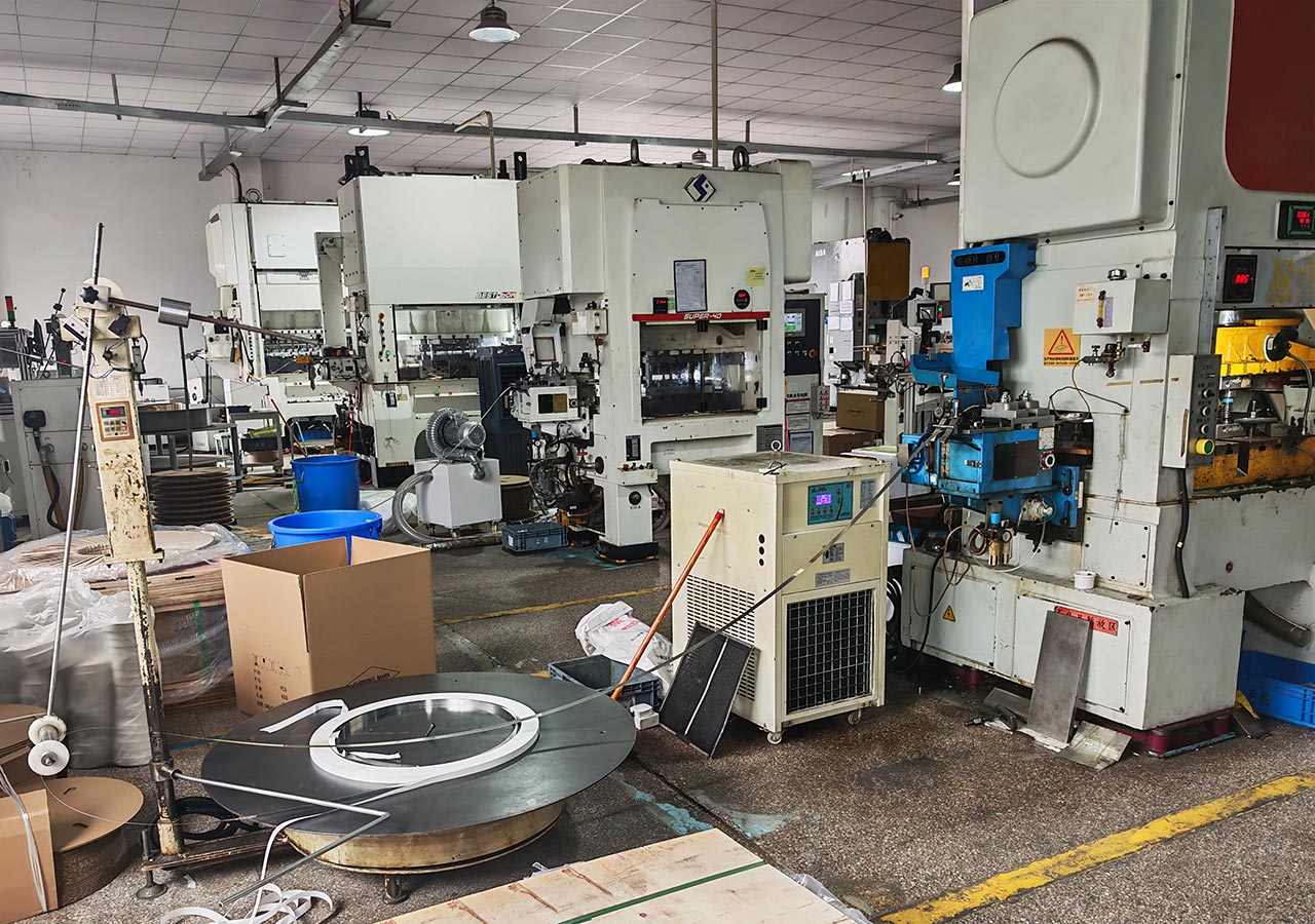
In a metal stamping production line, the stamping press and feeder must work together to keep material moving through the die at the correct time. The feeder delivers a programmed length of metal strip, while the press performs punching, bending, cutting, or forming operations.
If the feeding movement does not match the press cycle, the material may shift, the feed length may become inconsistent, or the die may be damaged.
So, how does a stamping press synchronize with a feeder? There are two common methods. A mechanical roll feeder uses a mechanical transmission connected to the press crankshaft, while an NC servo feeder receives electrical signals from the press to control feeding and material release. The suitable method depends on the press structure, control system, material specifications, and stamping requirements.
1. How Does a Mechanical Roll Feeder Synchronize with a Stamping Press?
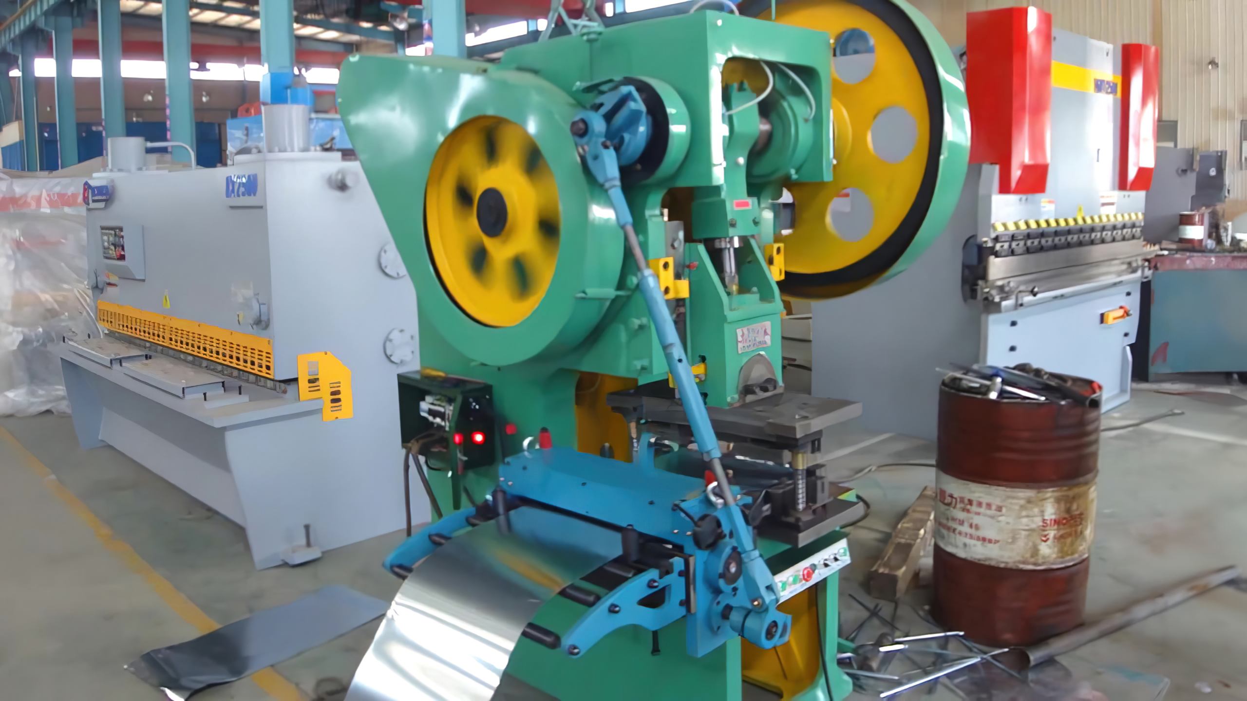
Mechanical roll feeders are commonly used with older mechanical stamping presses. Instead of using an independent servo motor, they obtain their driving motion directly from the press through a mechanical transmission system. A typical mechanical roll feeding system consists of a crankshaft-driven eccentric mechanism, connecting rod, transmission components, feeding rollers, and a mechanical release mechanism.
When the stamping press operates, the crankshaft rotates and drives the eccentric mechanism. The connecting rod transfers this movement to the feeder, causing the feeding rollers to rotate intermittently and move the metal strip forward. In a conventional single-stroke feeding arrangement, one complete crankshaft revolution corresponds to one feeding cycle. The mechanical transmission determines when the rollers move and how far the material advances.
Because the feeder is mechanically connected to the press, the feeding movement follows the crankshaft rotation without requiring a separate electronic feeding command. This arrangement is suitable for certain stamping applications involving relatively thin metal strips, fixed feed lengths, and moderate operating speeds.
Mechanical roll feeders have a relatively simple control structure and can be economical to maintain. However, changing the feed pitch usually requires mechanical adjustment. For manufacturers that frequently change dies or produce different components, these adjustments can increase setup time. The available feed length, material thickness, and operating speed also depend on the mechanical transmission and feeder capacity.
2. How Does an NC Servo Feeder Synchronize with a Stamping Press?
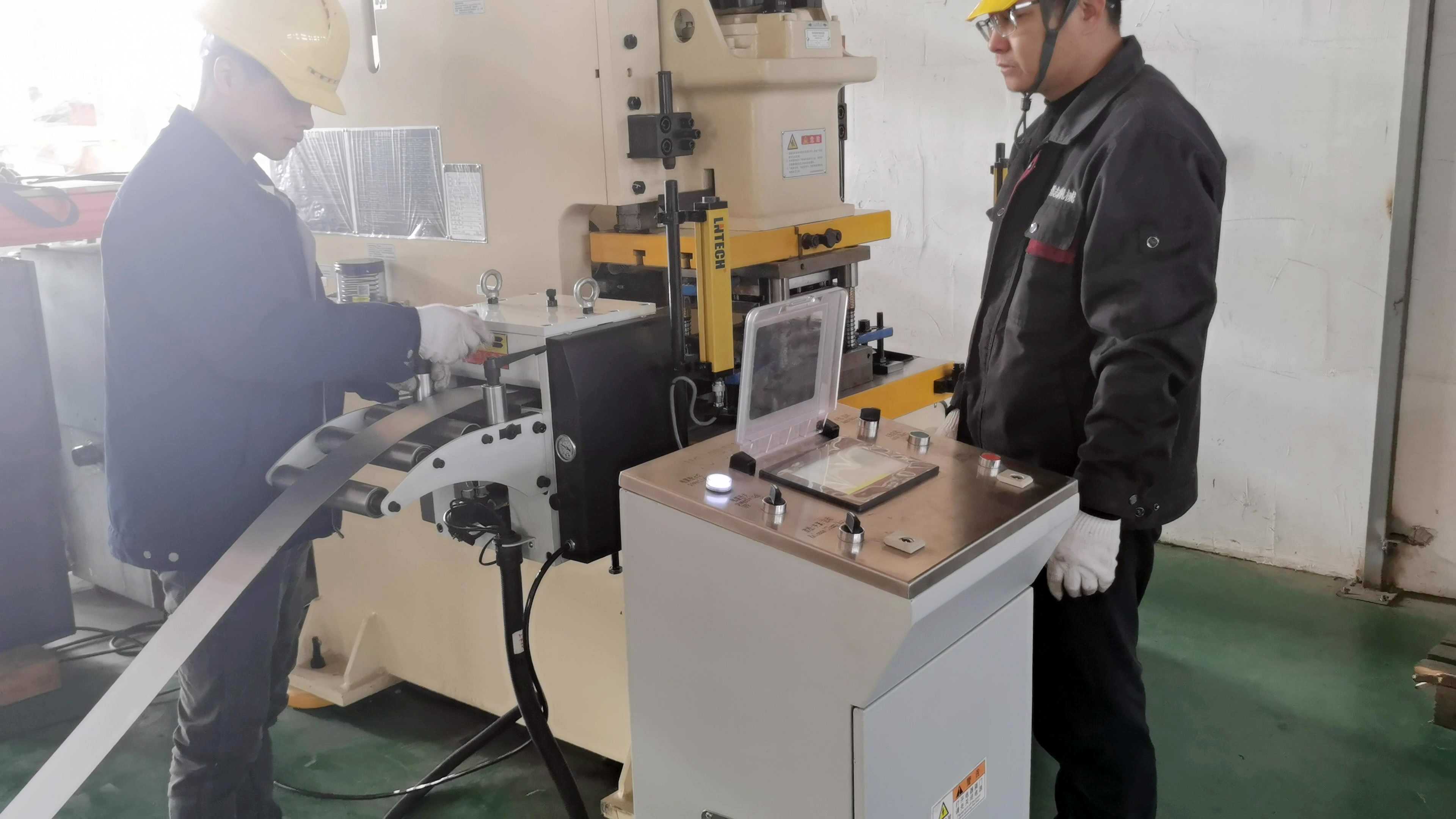
Unlike mechanical roll feeders, NC servo feeders use an independent servo motor to drive the feeding rollers. The stamping press provides electrical signals that tell the feeder when to start feeding and when to release the material. A typical NC servo feeder consists of a servo motor, servo drive, feeding rollers, transmission mechanism, material release device, controller, and electrical interface.
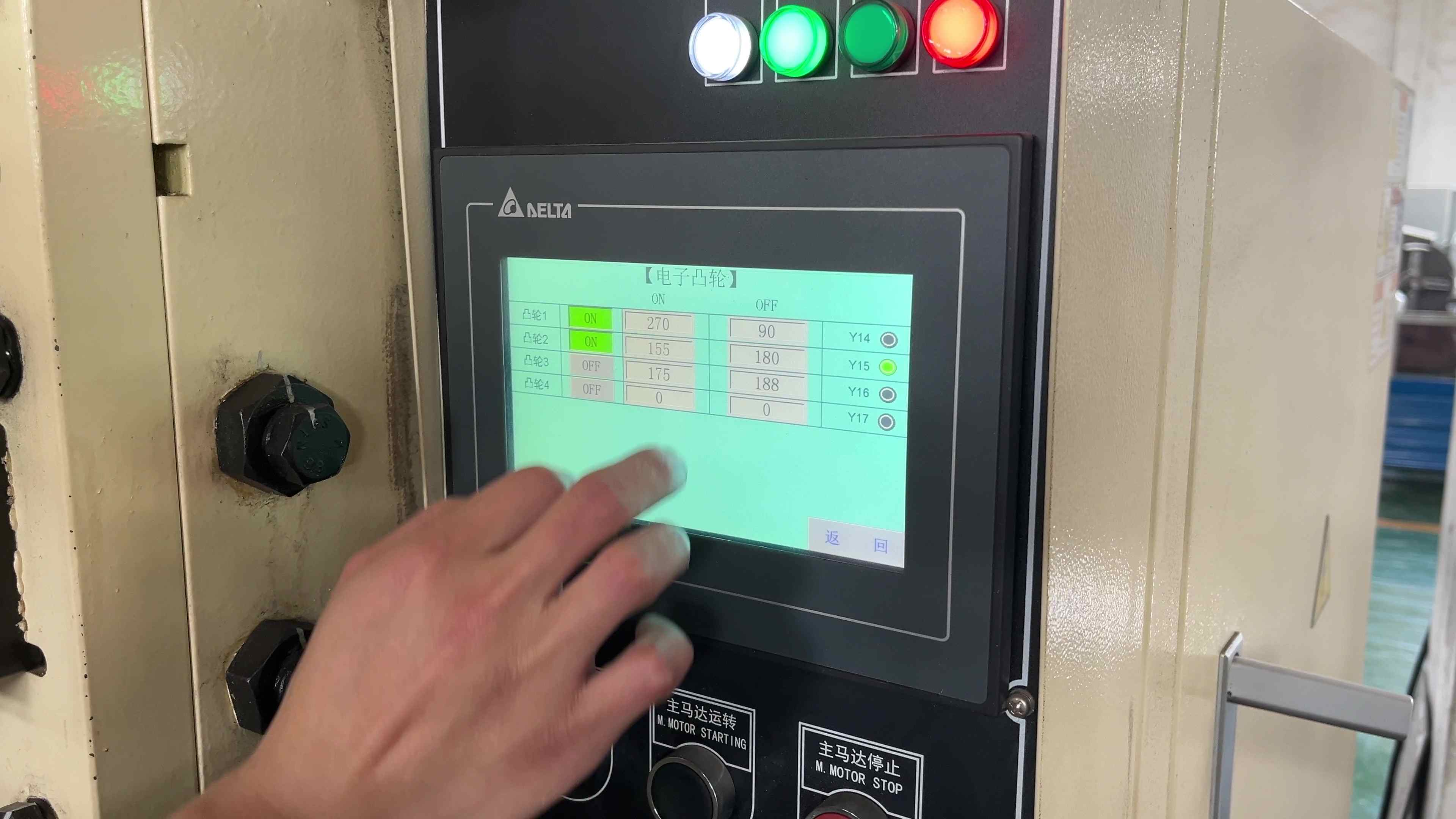
For many conventional pneumatic stamping presses, synchronization signals are provided by an electrical cam controller or electronic cam system. Three commonly used signal connections are:
Feed Signal: Commands the feeder to begin the programmed feeding movement.
Release Signal: Controls the roller release mechanism when the die pilot pins need to position the strip.
Common Terminal: Provides the common electrical reference or return connection for the relevant control circuit.
These signals are connected to the corresponding terminals of the feeder control system. The actual wiring depends on the press controller, feeder controller, signal type, and operating voltage. During automatic operation, the stamping press sends a feeding signal at a preset crankshaft position. After receiving the signal, the NC servo feeder moves the strip forward according to the programmed feed length and speed. The servo drive controls motor movement, while the encoder provides position feedback within the servo system.
Once the programmed feed length has been completed, the servo motor stops, and the feeding rollers maintain their grip on the strip until the next feeding or release command. If the feeder is equipped with a feed-completion output and the press controller supports the corresponding interlock, a completion signal can also be sent to the press control system. The feeder then waits for the next feeding command. This control method allows operators to adjust the feed length through the controller without modifying the mechanical transmission.
3. How Do Feeding and Release Angles Work During Stamping?
Synchronizing a feeder with a stamping press involves more than starting and stopping the feeding rollers. The feeding and release actions must also match the movement of the press slide and stamping die. During progressive die stamping, the strip should move forward only when the die is sufficiently open and the material can travel without interference. The feeding signal must therefore be set within an appropriate crankshaft angle range. The feeder needs enough time to complete the programmed movement before the die closes on the material.
When the die uses pilot pins for positioning, the feeding rollers may need to release their grip after the pilot pins enter the corresponding holes in the strip. This allows the pilot pins to make small positional corrections without resistance from the feeding rollers. In some stamping applications, the release angle may be adjusted around 180° to 185° of crankshaft rotation. However, this is not a fixed setting for every press. The actual release angle depends on the press angle reference, die structure, pilot pin engagement position, and feeding arrangement.
If the rollers release too early, the strip may move before the pilot pins are properly engaged. If they release too late, the rollers may resist the positioning movement of the die. Similarly, if the feeding signal is activated at the wrong crankshaft position, the feeder may begin moving the strip while the die is still engaged with the material. During commissioning, technicians should check the feeding angle, release angle, feed length, and press speed together. Controlled trial operation at a suitable reduced speed helps confirm that the feeding movement and die operation follow the intended sequence.
4. Mechanical Roll Feeder vs. NC Servo Feeder
Both mechanical roll feeders and NC servo feeders can synchronize with a stamping press, but their driving methods and adjustment requirements are different.
Comparison | Mechanical Roll Feeder | NC Servo Feeder |
|---|---|---|
Driving method | Mechanical transmission from press | Independent servo motor |
Synchronization | Mechanical linkage | Electrical cam or position signals |
Feed length adjustment | Mechanical adjustment | Controller parameter setting |
Feeding accuracy | Depends on transmission condition | Servo-controlled positioning |
Die changeover | May require mechanical adjustment | Feed parameters can be changed |
Press compatibility | Requires suitable mechanical drive | Requires compatible electrical signals |
Typical applications | Fixed-pitch stamping | Variable-pitch and automated stamping |
For older stamping presses already equipped with mechanical roll feeders, keeping the existing feeding system may be practical when production requirements remain unchanged. For manufacturers that frequently change products, use progressive dies, or require programmable feed lengths, an NC servo feeder offers greater adjustment flexibility. An older mechanical stamping press can also be equipped with an NC servo feeder if its electrical control system, available feeding window, and mechanical condition are suitable. The age of the stamping press alone does not determine whether a servo feeder can be installed.
5. How Do the Decoiler, Straightener, Feeder, and Stamping Press Work Together?
In an automatic metal stamping line, the equipment installed before the press must also supply material according to the production requirements. A conventional coil feeding line consists of a decoiler, straightener, NC servo feeder, stamping press, and progressive die. The decoiler supports and unwinds the metal coil. The straightener passes the strip through adjustable rollers to reduce coil curvature and improve material flatness. After straightening, the strip enters the NC servo feeder, which delivers the programmed feed length into the stamping die.
During continuous operation, the decoiler and straightener supply material to the feeder, while the feeder follows the timing signals from the stamping press. A material loop is commonly maintained between the upstream equipment and the feeder. Loop control sensors regulate material supply to help prevent excessive tension or slack.
For production lines requiring a more compact equipment layout, a decoiler straightener feeder combines decoiling, straightening, and servo feeding functions into one machine. The integrated servo feeding section synchronizes with the stamping press through electrical signals, while the decoiling and straightening sections operate according to their respective material supply requirements. A decoiler straightener can also be combined with a separate NC servo feeder when the material specifications or workshop layout require independent equipment. Depending on the machine configuration, these feeding systems can process steel, stainless steel, aluminum, and copper alloy coils. The appropriate equipment depends on material thickness, strip width, yield strength, coil weight, and surface requirements.
6. What Should Be Checked Before Connecting a Feeder to a Stamping Press?
Before purchasing or installing an NC servo feeder, customers should confirm whether their existing stamping press can provide the required synchronization signals. The first consideration is the press control system. Some stamping presses already have electrical cam outputs that can be connected to a servo feeder. Older machines may require additional signal interfaces or control system modifications.
The second consideration is the available feeding window. Even if the press provides a feeding signal, the feeder must have enough time to complete the programmed movement before the die closes. For example, a stamping press operating at 60 strokes per minute completes one press cycle every second. However, the entire second is not available for feeding. The actual feeding time depends on the crankshaft angle settings, die clearance, and operating sequence. The servo feeder must complete acceleration, material movement, and deceleration within the available feeding window.
Material specifications also affect feeder selection. Wider, thicker, or higher-strength metal strips may require greater feeding force and different roller or servo motor configurations. When requesting a feeder quotation, customers should provide the material type, strip width, thickness, coil weight, coil inner and outer diameters, feed pitch, and press operating speed. The press model, electrical circuit information, die structure, and available feeding and release signals are also useful for checking compatibility. Electrical connections and timing adjustments should be performed by qualified personnel according to the equipment manuals. Signal compatibility, grounding, interlocks, and press safety functions must be verified before automatic operation.
7. JINZHIDE Press Feeding Equipment and Technical Support
Changzhou JINZHIDE Machinery Technology Co., Ltd. manufactures metal coil feeding and stamping automation equipment, including decoilers, straighteners, NC servo feeders, decoiler straighteners, decoiler straightener feeders, and zigzag servo feeders. The company operates a manufacturing facility of approximately 5,300 square meters in Changzhou, China, producing feeding equipment for different metal stamping applications.
JINZHIDE NC servo feeders are available for material thicknesses from 0.1 to 3.2 mm in applicable configurations. Feed length and operating parameters can be adjusted according to the material specifications and production requirements. For wider or thicker materials, JINZHIDE also supplies integrated decoiler straightener feeder systems with different straightening roller structures, coil handling capacities, and servo feeding arrangements.
When customers need to connect feeding equipment to an existing stamping press, JINZHIDE can review the press model, electrical signal interface, material parameters, and stamping process before recommending a suitable configuration. During installation and commissioning, the technical team can assist with feeder positioning, feeding height adjustment, electrical signal connection, servo parameter setup, feeding angle adjustment, release timing, and press-feeder trial operation. These procedures help establish the correct operating sequence between the feeder and stamping press under the customer's production conditions.
Whether upgrading an older mechanical press or installing a new automatic stamping line, customers can provide their press model, material specifications, feed length, and operating speed to JINZHIDE for equipment selection and technical consultation.