




How to Choose a Metal Coil Feeder for Your Production Line
 Aug 24, 2026|
 View:96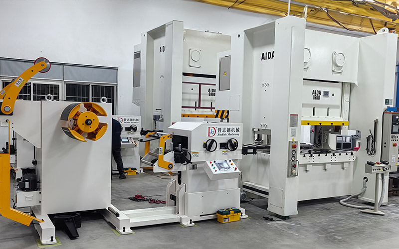
Selecting the wrong metal coil feeder can lead to costly downtime, material waste, and inconsistent part quality. This guide offers a practical, step-by-step approach to avoid these pitfalls. To select the right feeder, you must evaluate three core factors: your material specifications (width, thickness, weight), your production speed and accuracy needs, and how the feeder integrates with your decoiler, straightener, and press. Matching these factors to your production requirements ensures optimal performance. The machine's design must align with your metal processing workflow. Considering production efficiency and processing accuracy from the start helps you choose a feeder that delivers consistent results. The following sections detail each factor, from defining requirements to comparing technologies and making a cost-effective decision.
Key Takeaways
Evaluate your material's width, thickness, and coil weight first. These factors determine the feeder's required capacity and safety.
Match the feeder's speed and accuracy to your press's SPM and tolerance needs. Servo feeders offer high precision and programmability.
Choose between light-duty and heavy-duty feeders based on material thickness and strength. Light-duty suits thin materials up to 1.6 mm; heavy-duty handles thicker, stronger stock.
Ensure your feeder integrates smoothly with your decoiler and straightener. An integrated system simplifies synchronization and reduces errors.
Consider the total cost of ownership, not just the purchase price. Factor in energy, maintenance, downtime, and scrap to make a cost-effective decision.
Key Material Specifications for Feeder Selection
Evaluating Coil Width, Thickness, and Weight
Material and strip condition stand as the first consideration when choosing a metal coil feeder. You must measure coil width and thickness accurately before any other decision. Width tolerances typically run ±1/16 inch from the ordered dimension. Thickness measurements follow either minimal or nominal standards. Minimal thickness guarantees the material never falls below the target value. Nominal thickness allows variation, such as .0150 inch ranging from .0147 to .0153 inch. Most stamping operations prefer minimal thickness for consistent part quality.
Weight per foot provides a more reliable indicator of actual thickness than decimal measurements alone. Coil tags sometimes misrepresent the true yield. The optimal coil weight balances run time between coil changes against the time required for those changes. Maximizing coil weight minimizes production downtime. Consider a 0.250-inch thick by 24-inch wide steel coil with a 36-inch feed length at 30 SPM. A 10,000-pound coil yields roughly 163 parts with about 5.5 minutes of run time. Doubling to 20,000 pounds produces approximately 327 parts and 11 minutes of run time, increasing net yield by 48 percent. Thin materials behave differently. A 0.032-inch thick material at 24 inches wide with a 20-inch feed length at 30 SPM yields 2,300 parts from a 10,000-pound coil. The same coil weight provides over 77 minutes of continuous operation.
Underestimating coil weight creates serious safety hazards. An undersized feeder can buckle under excessive load, causing structural failure and potential injury. The best feeder based on coil width alone cannot compensate for inadequate weight capacity. Always verify the machine's rated weight against your heaviest production coil.
Matching Feeder Speed to Press SPM
The linear feed rate derives from feed length per stroke multiplied by press speed. The fundamental equation states: ideal feed rate equals feed length times strokes per minute. For a press running at 800 SPM with a 38.0-millimeter feed length, the ideal feed rate reaches 30,400 millimeters per minute, or 30.4 meters per minute.
Slip correction becomes essential for accuracy. Actual feed length per stroke equals π times effective roll diameter times revolutions per stroke times one minus slip ratio. Slip typically ranges from 0.1 to 0.5 percent at normal speeds. At 100 SPM, slip drops to roughly 0.05 percent, producing an actual feed of 38.04 millimeters per stroke. At 800 SPM, slip rises to about 0.6 percent, yielding 37.85 millimeters per stroke. The feed rate must adjust dynamically as SPM changes to maintain precision.
Selecting the Right Metal Coil Feeder Type
Once you have defined your material specifications and speed requirements, the next decision involves choosing among the three primary types of feeders: mechanical, pneumatic, and servo-driven. Each type serves distinct production needs. Understanding their differences prevents costly mismatches between the feeder and your stamping operation.
Servo-Driven vs. Mechanical Feeders
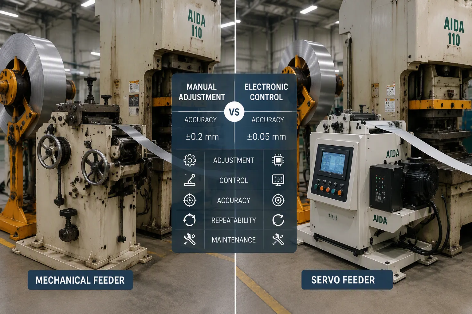
Servo-driven feeders use a microprocessor-controlled motor to advance the strip. This design delivers exceptional precision. A servo feeder can hold feed length accuracy to ±0.001 inches, with repeatability of ±0.002 inches. These tolerances remain consistent across thousands of strokes. The operator can adjust feed length electronically during production. Programmable pattern control allows non-consistent movements, such as a 2-inch, 2-inch, then 3-inch sequence. This flexibility suits progressive dies and multi-step stamping operations. Servo feeders also communicate with automation systems, enabling self-diagnosis and auto-correction.
Mechanical feeders draw power directly from the press through a linkage. They offer high speed and locked-in timing. For fixed, high-volume jobs, a mechanical feeder performs admirably. However, feed length adjustment requires manual intervention. The operator must change gears or replace mechanical rods. This process is time-consuming and prone to error. Mechanical feeders lack electrical control, so they cannot receive feedback from or provide signals to automation. They also risk marring the material surface during feeding.
Feature | Pneumatic (Air) Feeder | Mechanical (Roll) Feeder | NC Servo Feeder |
|---|---|---|---|
Cost | Low | Moderate | Relatively High |
Feeding Speed | Low to Moderate | Very High | Moderate to High |
Feeding Accuracy | Moderate (±0.2 mm) | High (±0.05 mm) | Very High (±0.01 to ±0.05 mm) |
Feed Length Adjustment | Manual (Stop mechanism) | Manual (Gears/Rods) | Electronic (HMI/PLC) |
Best Application | Low-speed, simple parts | High-speed, fixed-length stamping | Progressive dies, multi-step, high precision |
The table above presents a general comparison. Note that servo accuracy figures vary by manufacturer and model. The ±0.001-inch precision mentioned earlier represents a premium servo system. Both mechanical and servo systems vastly outperform pneumatic feeders, which rely on compressed air and die pilots for positioning. Air feeders cost less upfront but struggle with timing at high speeds.
Pneumatic feeders suit low-speed operations with simple feed requirements. They lack the precision and programmability of servo systems. For most modern stamping lines, servo-driven units provide the best balance of accuracy, flexibility, and integration capability.
Light-Duty vs. Heavy-Duty Configurations
The material thickness and width you measured earlier determine whether you need a light-duty or heavy-duty configuration. These two classes of feeders differ substantially in construction and capability.
Feature | Light-duty (NCF series) | Heavy-duty (RNC series) |
|---|---|---|
Material thickness | 0.1–1.6 mm | 0.3–6.0 mm |
Coil width capacity | Up to 400 mm | Up to 1300 mm |
Feeding accuracy | ±0.15 mm | ±0.1 mm |
Maximum feeding speed | 20 m/min | 20 m/min |
Programmability | Standard servo control | Up to 20 preset feed lengths |
Material strength | Standard materials | Yield ≤245 N/mm², tensile ≤392 N/mm² |
Light-duty feeders handle thin materials up to 1.6 mm thick. They suit applications such as electronics components, small brackets, and light stampings. The machine features a simpler frame and lighter rolls. This configuration keeps initial investment low while delivering adequate precision for most thin-strip jobs.
Heavy-duty feeders accommodate thicker stock up to 6.0 mm. They include reinforced frames and pneumatic-release systems. These feeders handle high-strength materials with yield strength up to 245 N/mm². Heavy-duty units often feature advanced PLC controls with multiple preset feed lengths. This programmability proves valuable for job shops that switch between parts frequently.
The economics of selecting a coil feed line vary by application. A light-duty feeder costs less initially. It also requires less floor space and simpler installation. However, choosing a light-duty unit for a heavy-stamping application leads to premature wear and frequent breakdowns. Conversely, a heavy-duty feeder for thin materials wastes capital and floor space. Match the feeder class to your actual production demands. Consider future growth as well. A feeder rated slightly above your current needs provides a safety margin without excessive cost.
The right choice among these types of feeders depends on your specific application scenarios. A servo-driven light-duty unit serves precision electronics stamping well. A mechanical heavy-duty feeder excels in high-volume automotive parts production. Evaluate your part mix, batch sizes, and tolerance requirements before committing to a configuration.
Line Integration and Choosing a Suitable Decoiler
Matching Feeder with Decoiler and Straightener
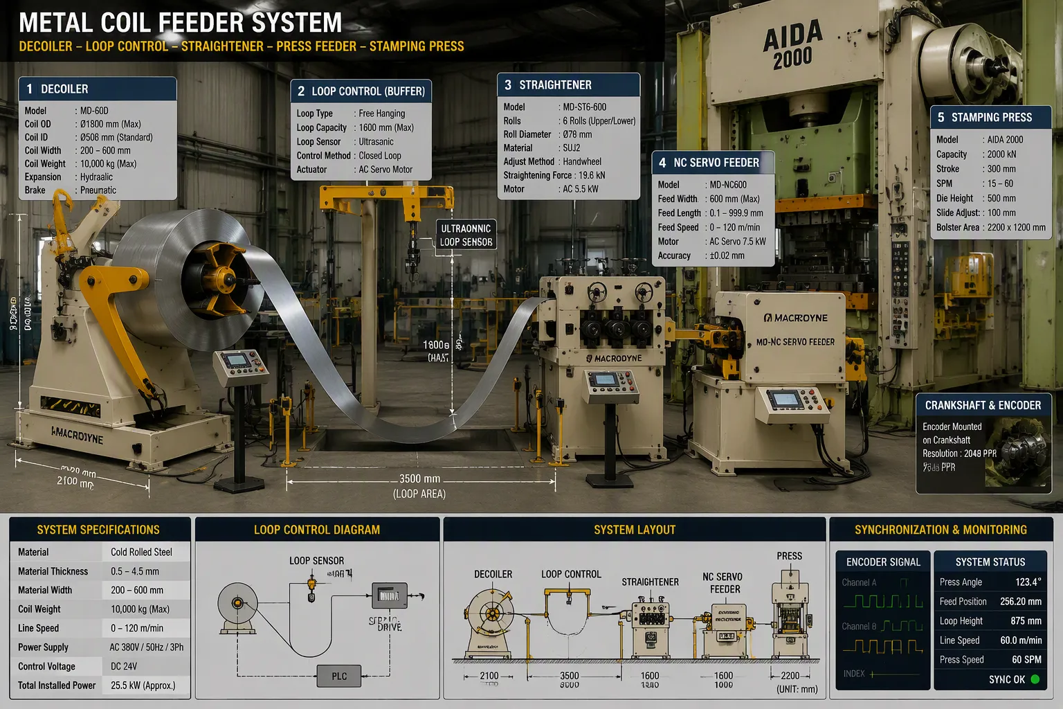
A metal coil feeder does not operate in isolation. It functions as part of a coordinated system that includes the decoiler, straightener, and press. Treating these components as separate purchases from different suppliers often creates synchronization problems. Each machine may have different control protocols, speed ranges, or communication interfaces. These mismatches lead to timing errors, material jams, and inconsistent feed lengths.
The line layout and upstream equipment determine how well your feeder performs. Before installation, collect comprehensive data: equipment dimensions, space requirements, system layout drawings, coil weight and length capacities, and feeding speeds. This information prevents surprises after the machines arrive. A suitable decoiler must match your coil inventory's weight range, typically 1 to 20 tons, and accommodate your strip width. The straightener must handle your material thickness while delivering the flatness your stamping process requires.
Loop control plays a critical role in this integration. Between the decoiler and straightener, a free-hanging loop of material acts as a buffer. This loop separates the continuous unwind of the decoiler from the intermittent demand of the press. Without it, the sudden jerk of the press feeder creates tension spikes that distort feed accuracy. Loop sensors monitor the loop size and signal the decoiler to speed up or slow down. This feedback ensures consistent material flow throughout the cycle.
Synchronization methods vary by application. Basic signal interlock mode uses electrical signals between feeder and press. The press reaches top dead center, sends a feed signal, and waits for confirmation. This achieves a standard one-stroke, one-feed cycle. For high-speed and precision stamping, encoder position synchronization reads the press crankshaft position directly. The feeder delivers material within a safe motion window, completing the feed before die closure. This method suits progressive dies where timing precision is critical.
An integrated solution simplifies these compatibility challenges. The JINZHIDE Decoiler Straightener Feeder combines decoiling, straightening, and feeding into one compact unit. This three-in-one design eliminates the need to match separate control systems. It reduces floor space requirements and simplifies installation in existing facilities. The integrated unit connects easily with presses, shears, and blanking systems. Automatic threading and hydraulic features reduce manual handling and setup time. For manufacturers upgrading an existing line or building a new one, this approach lowers installation complexity while ensuring single-point responsibility for performance.
Evaluating Feed Pitch Accuracy and Material Flow
Feed pitch accuracy directly affects part quality in progressive die stamping. A small error of 0.002 inches per stroke compounds across multiple strokes. This accumulation leads to scrap parts and misaligned features. High-value products demand extremely tight tolerances. A servo feeding system with closed-loop control corrects for slip in real time. This correction is essential when integrating a feeder with existing equipment.
Material flow depends on the coordination between decoiler, straightener, and feeder. The decoiler adjusts its rotational speed to match downstream demand. A sensor or loop-control system detects changes in material position or tension. The controller adjusts the decoiler motor accordingly. This coordinated control maintains a stable material loop. The uncoiled strip enters the straightener, where coil curvature and deformation are reduced. The leveled strip then moves toward the servo feeder, which controls feeding length and positioning before the material enters the press.
High-speed decoiling requires rapid acceleration and deceleration with stable synchronization. The machine must respond quickly to loop sensor signals without overshooting. Automated coil unwinding systems communicate with downstream equipment through sensors and control signals. If the decoiler releases material too quickly or too slowly, the material loop becomes unstable. This instability affects feeding accuracy and can cause misfeeds.
Integrated systems often provide better synchronization because the control logic resides in one place. The JINZHIDE unit coordinates all three functions internally. This eliminates the communication delays that occur between separate machines. For a metal coil feeding line, this coordination translates into consistent feed pitch accuracy and smooth material flow. The result is fewer rejected parts, less material waste, and higher overall productivity.
Final Decision: Cost, ROI, and Expert Guidance
Calculating Total Cost of Ownership
The purchase price of a metal coil feeder represents only the beginning of your financial commitment. A complete total cost of ownership analysis reveals the true economic picture. Capital and installation costs include machine price, shipping, customs, foundation work, rigging, commissioning, and operator training. These upfront expenses vary significantly by region and facility readiness.
Energy consumption forms another ongoing cost component. An NC servo feeder draws power only during the feed stroke. Mechanical and hydraulic systems consume electricity continuously during operation. This difference compounds over thousands of production hours. Material yield and scrap rates also affect your bottom line directly. Feeding accuracy determines scrap frequency. Tighter tolerances reduce misfeeds and edge damage, preserving valuable material.
Maintenance and spare parts demand careful budgeting. Rollers, gears, bearings, seals, and electronic boards all require periodic replacement. A documented maintenance schedule with published parts prices helps you forecast these expenses accurately. Downtime and quality losses often outweigh all other factors combined. Even two unscheduled stops per month can exceed a price difference of several thousand dollars between competing feeders.
Hidden costs frequently surprise first-time buyers. Foundation work, training, customs duties, import brokerage, and consumables such as lubricants and filters add up quickly. Tooling damage from misfeeding creates another expensive consequence. Consider residual value and upgrade potential as well. A reputable brand with CE certification and documented service history retains resale value. Such equipment can be upgraded rather than scrapped when production demands change.
Different line configurations carry distinct cost profiles. Paddle loop systems, underslung designs, and synchronous lines each present unique economics. Your specific application determines which configuration delivers the best return. The most expensive machine does not always provide the lowest total cost. A feeder matched precisely to your production requirements minimizes waste and maximizes uptime.
Consulting with Manufacturers for Custom Solutions
Equipment manufacturers offer expertise that transcends any catalog specification. JINZHIDE provides free technical consultation for coil handling and press automation. This service helps you understand your exact needs before committing capital. Their engineers address common challenges including changed product specifications, new manufacturing methods, increased output demand, and limited factory space.
Customized solutions solve problems that standard equipment cannot. A suitable decoiler paired with the right feeder transforms an underperforming line. JINZHIDE offers compact coil feeder lines that reduce space requirements dramatically compared to conventional equipment needing large floor areas or loop pits. Modular upgrades modernize performance without requiring complete equipment replacement. This approach reduces capital expenditure while delivering new functionality.
Safety upgrades represent another critical consultation area. Installation of safety gates, photoelectric sensors, and other press automation safety components ensures compliance with international standards. These additions protect workers and prevent costly accidents. JINZHIDE has served over 60 countries with hundreds of thousands of customers. Their engineers travel worldwide for on-site installation, commissioning, and training. With more than 12 after-sale engineers, they can reach your workshop within 72 hours globally.
The right manufacturer partnership extends beyond the initial sale. Ongoing support maximizes your machine's lifespan and productivity. When you select the right feeder with expert guidance, you gain a partner invested in your operational success.
Selecting the right feeder follows a clear process. First, define your material specifications: width, thickness, and coil weight. Second, determine the required feed speed and accuracy. Third, choose the feeder type — servo, mechanical, light-duty, or heavy-duty — that matches those needs. Fourth, ensure compatibility with a suitable decoiler and straightener.
The most expensive feeder does not always deliver the best results. The ideal machine matches your specific requirements for efficiency, precision, and reliability. This alignment helps enhance production stability across your line.
Contact equipment manufacturers with your parameters in hand. Expert consultation proves invaluable. JINZHIDE offers such consultation. Their integrated Decoiler Straightener Feeder system simplifies compatibility. It ensures seamless integration and optimal performance.
FAQ
What is the main difference between servo and mechanical feeders?
Servo feeders offer electronic programmability and high precision for complex jobs. Mechanical feeders provide locked-in timing and high speed for fixed, high-volume production. The choice depends on your need for flexibility versus consistent, simple operation.
How do I know if I need a light-duty or heavy-duty feeder?
Check your material thickness and width. Use light-duty models for thin materials up to 1.6 mm. Choose heavy-duty configurations for thicker stock, up to 6.0 mm, and for handling high-strength materials. Matching the class to your actual production prevents premature wear or wasted capital.
Why is feed pitch accuracy so important?
Inaccurate feed length compounds with each press stroke. This leads to misaligned parts in progressive dies, creating scrap. High-value stamping requires tight tolerances, often maintained by servo systems with real-time slip correction.
What should I consider for integrating a feeder with my existing line?
Ensure compatibility between the feeder, decoiler, and straightener's control systems and speed ranges. Mismatches cause timing errors. An integrated unit like a Decoiler Straightener Feeder simplifies this by combining all three functions with a single control system, ensuring smooth material flow.
Can one feeder handle all the different types of materials and jobs in my shop?
Not typically. Different jobs have unique requirements for speed, precision, and material strength. A single feeder model is usually optimized for a specific range of applications. Consulting with a manufacturer helps select the right model from the available types of feeders for each production cell.
What are the challenges of high-speed decoiling?
High-speed decoiling demands rapid motor response to maintain a stable material loop. An unstable loop causes tension spikes and misfeeds. A properly synchronized high-speed decoiler uses sensors and feedback control to adjust speed instantly, ensuring consistent material flow to the feeder and press.
How does coil weight affect feeder selection?
Coil weight is a primary safety factor. An undersized feeder can buckle under excessive load, risking equipment failure and injury. Always verify the machine's rated weight capacity against your heaviest production coil before purchase.