




How to Choose the Right Servo Feeder in 2026
 Sep 04, 2026|
 View:147
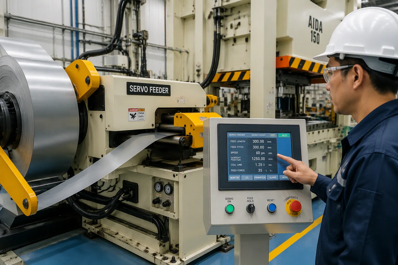
The servo feeder decides your stamping line's throughput, part quality, and material yield — yet it remains one of the most frequently mis-specified machines in the line. Specify it by coil width alone, and you may discover roll slippage, misfeeds, or motor overload a few months after commissioning. This guide walks through the five criteria that actually drive the decision: material width and thickness, yield strength, feed length and accuracy, press speed, and line layout. You will get field benchmarks, an honest total-cost comparison against mechanical and pneumatic feeders, and a sizing checklist you can hand directly to your supplier.
Whether you are retrofitting a single press or commissioning a complete automated stamping line, the same selection logic applies. And the stakes keep rising: tighter tolerances, higher-strength materials, and Industry 4.0 connectivity now sit on top of the classic speed-and-accuracy equation.
By the end, you will know exactly what to specify — and how to evaluate a servo feeder supplier who can support your line for the next decade, not just survive the installation.
Key Takeaways
Specify five inputs first: maximum coil width, thickness, yield strength, feed length, and press speed (SPM).
Quality NC servo feeders hold ±0.02 mm repeatability — sufficient for progressive dies and multi-stage transfer work.
Stamping round or nested parts? A zigzag servo feeder improves material utilization by up to 20%.
High-strength steel changes the equation: above ~245 N/mm² yield you need higher servo torque, reinforced rolls, and hydraulic threading.
Standalone servo feeders suit retrofits; a 3-in-1 compact line cuts footprint from ~7 m to ~3 m and setup from 30 min to 8 min.
Compare total cost of ownership, not sticker price — servo systems typically break even within 12–18 months through scrap and labor savings.
Demand open fieldbus protocols and upgradable, predictive-maintenance-ready controllers for Industry 4.0.
Buy from a supplier with ISO9001 certification, in-house manufacturing, and documented global service coverage.
The 5-Minute Servo Feeder Sizing Checklist
Before requesting quotations, gather the five data points below from your stamping line. Providing them upfront ensures you receive an accurate engineering proposal instead of a generic price list — and it eliminates most back-and-forth during the RFQ stage.
Parameter | What to Measure / Confirm |
|---|---|
Max coil width & thickness | Record the widest and thickest material you plan to run. Note: running maximum width and maximum thickness simultaneously requires a heavy-duty model, so state both extremes clearly. |
Yield strength (material grade) | Standard mild steel is ~245 N/mm². If you stamp high-strength steel (HSS), stainless, or aluminum alloys, specify exact tensile strength so the supplier can size servo torque and roll rigidity correctly. |
Feed length & press speed (SPM) | Check your progressive die pitch and the press's maximum strokes per minute. High-speed lines (>400 SPM) may require dual-servo or release-pin configurations. |
Pass line height | Measure from factory floor to the center of your die entry, and confirm the feeder's vertical adjustment range covers it for every tooling setup. |
Part geometry (scrap strategy) | Producing round parts (washers, motor cores, cookware)? Specify a zigzag servo feeder to stagger the layout and save up to 20% on raw material. |
What Is a Servo Feeder Machine?
A servo feeder machine is the precision material-delivery system positioned between your decoiler/straightener and the stamping die. Instead of mechanical linkages or compressed air, it uses a servomotor to rotate the feed rolls under closed-loop digital control. The controller commands an exact rotation angle for each press stroke, while the encoder continuously verifies actual roll position and corrects any deviation instantly. The result is consistent material advancement, cycle after cycle, regardless of job changes.
Core Components and Operation
Every servo feeder contains three essential subsystems: the servo motor (driving the feed rolls through a precision gearbox), the feed roll assembly (gripping and advancing the coil), and the programmable controller (storing multiple feed recipes). When the press completes its stroke and signals readiness, the controller advances the material exactly to the programmed feed length; sensors verify position before the next stroke begins. This synchronization happens within milliseconds, and job changeover becomes a touchscreen selection rather than a mechanical re-adjustment.
Key Benefits of Servo Precision
Servo-driven feeding delivers measurable advantages over alternative technologies. Facilities switching from pneumatic feeders typically see scrap fall from 2–3% to 0.5–1% on tight-tolerance jobs. Controlled velocity profiles extend die life by 2–4 times compared with uncontrolled impact feeding, and programmable deceleration before punch breakthrough protects expensive tooling. Changeovers that take 10–15 minutes on air feeders complete in 2–5 minutes using saved recipes. These gains — not the technology itself — are what pay for the machine.
Typical Stamping Applications
Different servo feeder types serve distinct production niches. High-speed servo feeders excel at motor core stamping and silicon steel lamination, where rapid cycling must not sacrifice feeding accuracy. Zigzag servo feeders handle circle blanking and nested layouts for cookware, washers, and round covers. NC servo feeders cover general stamping, punching, and blanking across automotive, appliance, electronics, and hardware components. Specialized configurations paired with cutting machines perform fixed-length shearing and sheet preparation.
Servo Feeder vs. Mechanical and Pneumatic Feeders
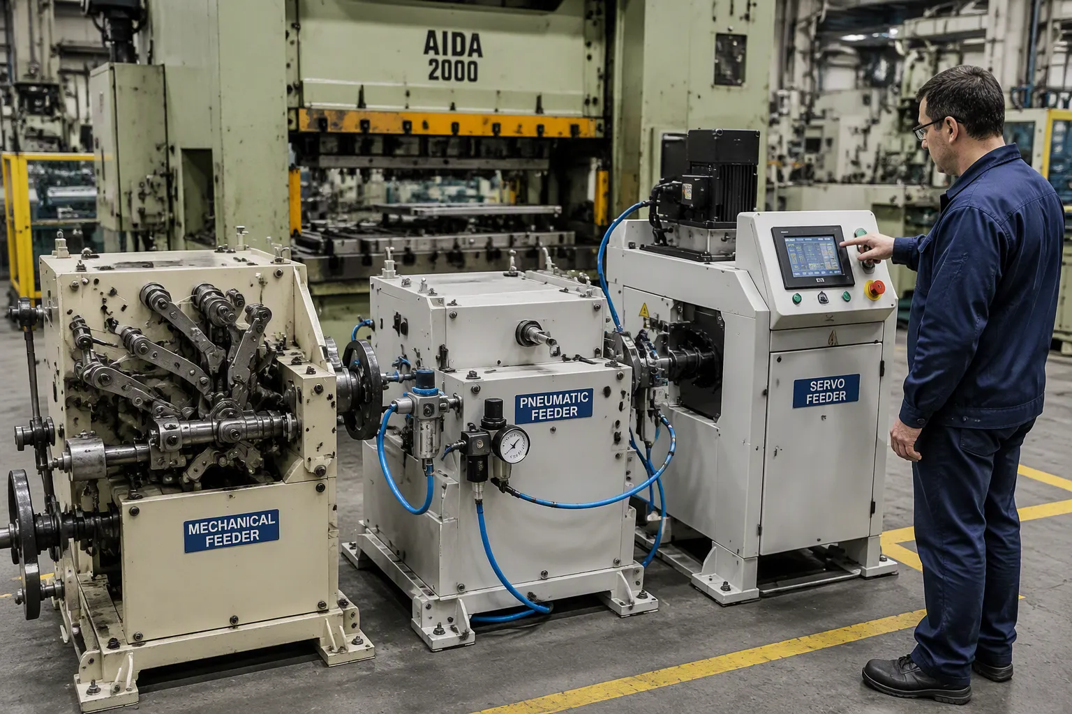
Stamping line operators still face a fundamental technology choice. Mechanical feeders dominated early press lines; pneumatic feeders arrived as a lower-cost alternative. Both remain in older facilities, and both still make economic sense in narrow cases — long runs of a single, simple part. Yet modern production demands expose their limits, which is why servo technology now leads new installations.
Limitations of Mechanical Feeders
Mechanical feeders operate through linkages connected to the press crankshaft, so feed length is fixed by linkage geometry. Changing a job means physically adjusting cams and connecting rods — stop production, measure, test, repeat. Accuracy also degrades with wear: linkage joints loosen, feed length drifts, and operators compensate with constant manual tuning. Because the press mechanically drives the feeder, there is no independent control interface, making automation integration nearly impossible.
Limitation | Description |
|---|---|
Flexibility | Very limited; restricted to fixed, repeatable parts, making it unsuitable for frequent job changes. |
Feed length change | Slow and cumbersome; set by mechanical linkage, requiring significant downtime compared with servo units. |
Accuracy over time | Degrades as linkage joints wear; feed length drifts and requires constant manual compensation. |
The Real Cost of Pneumatic Feeders
Pneumatic feeders win on capital expenditure: an air feeder costs a fraction of a servo feeder machine. For budget-conscious shops running simple parts, that gap matters. The problem is operational expenditure — compressed air consumption, higher scrap, slower changeovers, and one extra operator — which quietly erodes the initial saving year after year. The right comparison is therefore total cost of ownership (TCO), not purchase price.
Factor | Servo Feeder | Air Feeder |
|---|---|---|
Initial investment (CAPEX) | Higher | Lower |
Labor reduction | 1–2 operators saved | ~1 operator saved |
Productivity gain | 40–60% | 20–30% |
Scrap rate (tight-tolerance jobs) | 0.5–1% | 2–3% |
Changeover time | 2–5 min (saved recipes) | 10–15 min (manual) |
Typical payback of servo premium | 12–18 months | — |
An illustrative example shows why. Take a shop running 100,000 parts monthly at $0.50 material cost per part. Moving from 2.5% scrap (air feeder) to 1% scrap (servo) saves 1,500 parts monthly — roughly $9,000 annually in material alone. Add faster changeovers (200 per year at ~10 minutes saved each) and one fewer operator, and the price gap between the two technologies is typically recovered within 12–18 months. After that, every additional year is pure margin in the servo system's favor. The cheapest feeder to buy is rarely the cheapest feeder to own.
Why Servo Feeders Lead Modern Lines
Servo feeders deliver consistent, micron-level positioning on every stroke — the repeatability progressive dies with narrow tolerance windows depend on. They handle a wide range of materials, thicknesses, and feed lengths without mechanical reconfiguration, synchronize with virtually any power press, and support SMED-style rapid changeover. Industry surveys consistently show servo technology taking the majority share of new feeder installations, and that share keeps climbing as material costs and tolerance requirements rise.
Attribute | Mechanical Feeder | Servo Feeder |
|---|---|---|
Feeding accuracy | Medium, degrades with wear | High, stable over time |
Job adjustment | Limited, mechanical | Flexible, programmable |
Automation readiness | Low | High (Industry 4.0 ready) |
Total cost of ownership | Lower purchase, higher operation | Higher purchase, lower operation |
Material and Feed Specifications
Material specifications form the foundation of every servo feeder selection. They determine motor torque, roll diameter, and structural rigidity. A mismatch between material requirements and feeder capacity creates slippage, marking, and quality issues that no amount of commissioning can fix. Understanding these specifications before contacting a servo feeder supplier prevents costly errors.
Evaluating Material Width and Thickness
Width and thickness together define feeder capacity. Standard NC servo feeders cover coil thickness from roughly 0.1 to 3.2 mm at widths up to 1,300 mm; heavy-duty models extend to 6.0 mm, and dedicated high-strength lines reach 9.0 mm at widths up to 2,000 mm. These ranges cover most coil-fed applications across automotive, appliance, and electronics manufacturing.
Crucially, maximum width and maximum thickness cannot be combined freely. As coil width increases, the allowable thickness at full width decreases, because wider coils raise the moment of inertia on the feed rolls while thicker material demands higher torque. A feeder that comfortably handles 3.2 mm at 600 mm width may need a larger servo and reinforced roll assembly to run the same gauge at 1,300 mm. Always present your supplier with the real width/thickness combinations you run, not just the two extremes.
Roll configuration matters here. A four-roll design provides twice the surface contact at half the air pressure, reducing slippage and surface damage on critical materials while maintaining the same repeatability as two-roll models. Material type also influences selection: pre-painted or polished surfaces need gentler handling and coated rolls, while aluminum behaves differently from steel at identical dimensions.
When Your Material Is High-Strength Steel
Most standard feeders assume material with yield strength at or below 245 N/mm². Automotive chassis parts, heavy-duty brackets, and construction machinery components increasingly use high-strength steel (HSS) far beyond that limit — and HSS changes the physics of feeding. Higher yield strength means greater springback, higher resistance to bending around the feed rolls, and a real risk of coil loosening, deviation, and slippage during acceleration.
For these applications, specify a dedicated high-strength coil feeding line: higher-torque servo motors, reinforced roll assemblies, a heavy-duty hydraulic pressing arm, and hydraulic threading with active material feeding that prevents coil loosening and deviation. JINZHIDE's HSS lines handle yield strength up to 613 N/mm² and tensile strength up to 980 N/mm², with thickness from 0.8 to 9.0 mm, using an 11-roll leveling head (6 upper / 5 lower) for stable flattening of thick, high-tension coil. If HSS is on your roadmap — even for future programs — size the feeder for it now.
Determining Feed Length and Accuracy
Modern servo feeders accommodate feed pitches up to 999.99 mm at feeding speeds up to 16 m/min, covering everything from small electronic connectors to large structural parts. High-quality units hold ±0.02 mm repeatability on standard precision models; heavy-gauge HSS lines hold ±0.2 mm at a 500 mm feed, which is more than adequate for chassis-class components.
Real-world accuracy, however, depends on factors beyond the feeder itself. The feeding center line must align precisely with the die entry, and pass line height adjustment must cover every tooling setup. Different products demand different tolerance levels: progressive dies for electronic connectors may be unusable beyond ±0.02 mm deviation, while structural parts tolerate wider variation. Tighter feeding accuracy produces more consistent parts, which reduces scrap and stabilizes downstream assembly.
How Coil Quality Affects Feeding Accuracy
Even a perfectly specified feeder cannot rescue poor coil. Coils that are too narrow cause gap and jitter at the guide pins; coils that are too wide get compressed and deformed during feeding. Slitting precision therefore directly determines feeding precision. Waveform defects are equally critical: mild swelling under 2 mm over a 2,000 mm length remains manageable, but severe corrugation exceeding 5 mm over the same length makes accurate feeding impossible. Inspect coil quality — camber, wave, and width tolerance — before loading, and treat supplier coil certificates as part of your feeding specification.
The most common specification error we see is a feeder sized on width alone. Thickness, tensile strength, and surface finish decide the roll configuration, the servo motor, and the coating. Get those three right, and the line behaves from day one.
— JINZHIDE Application Engineering Team
Press Compatibility and Line Integration
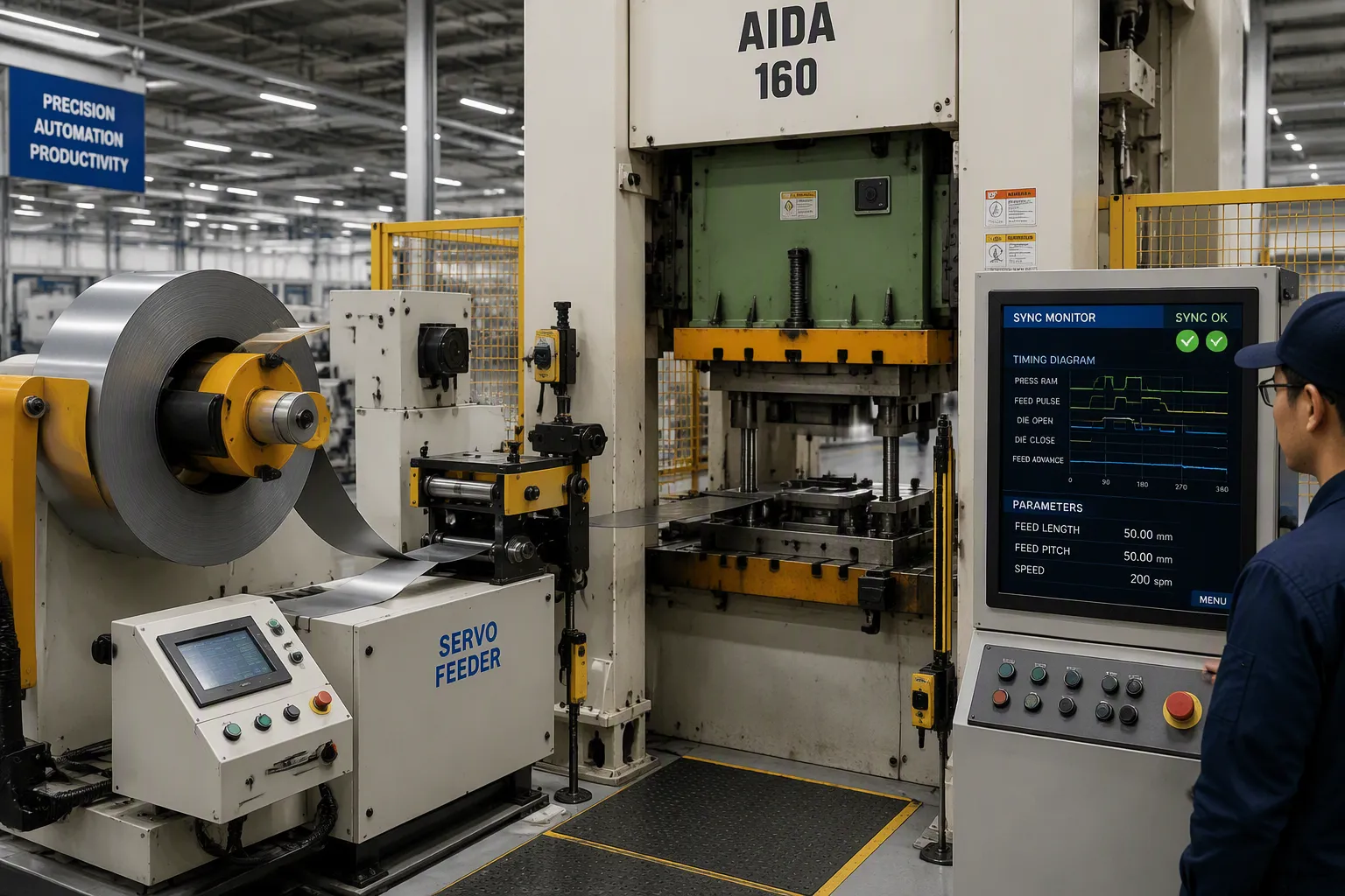
A servo feeder machine must function as one unit with your press. It receives signals from the press control system and advances material at the exact moment the press completes its stroke. Poor synchronization creates misfeeds, double hits, and damaged tooling — so integration success depends on matching control protocols and understanding timing requirements before purchase.
Synchronizing Feeder Motion with Press Stroke
Manufacturers use several techniques to align feeder motion with press timing. Priority mode selection lets operators define which machine leads the sequence: feed-before-press suits applications requiring material positioning before die closure, while press-before-feed works where die clearance is needed before advancement. Press/feeder synchronous checking continuously verifies alignment and triggers an immediate stop on misalignment, preventing collisions before they damage expensive tooling. For multi-feed lines, a single-control architecture drives several servo feeds from one controller, keeping speed and position coordinated in real time.
Synchronization Technique | Description |
|---|---|
Priority mode selection | Operator defines whether feeder or press leads the timing sequence. |
Press/feeder synchronous checking | Continuous verification that feeder motion aligns with press stroke; automatic stop on misalignment. |
Single-control architecture | One controller drives multiple feeds for real-time speed and position coordination. |
Space vs. Efficiency: Standalone Feeder or 3-in-1 Compact Line?
When integrating a servo feeder, you must also choose the line architecture. A traditional setup — 2-in-1 decoiler-straightener plus a separate servo feeder — offers maximum flexibility for specialized straightening requirements, but occupies around 7 meters of floor space, requires each machine to be adjusted separately, and can take up to 30 minutes for die-change setup.
A 3-in-1 decoiler straightener feeder integrates uncoiling, leveling, and servo feeding into a footprint of only about 3 meters, saving 2–3 meters of line length. Material threading completes in a single pass, feeder height adjusts electrically, and die-change setup drops to roughly 8 minutes. For new lines, space-constrained shops, or operations with frequent job changes, the 3-in-1 is usually the better investment; the standalone configuration remains the right call when retrofitting existing straighteners or handling unusual materials. A detailed comparison is available in JINZHIDE's guide to 2-in-1 vs. 3-in-1 sheet metal feeders.
Surface Quality and Material Handling
Material handling directly affects finished part appearance. Painted, polished, or pre-finished surfaces require special attention, because standard steel rollers can scratch them during feeding. Specify polished chrome rolls, nylon- or PU-coated rollers, and protected threading surfaces for these materials. Roller pressure must also match material thickness and finish: insufficient pressure causes slippage, excessive pressure leaves marks. Adjustable, repeatable pressure settings let operators dial in each material type once and reproduce it from saved recipes, preserving surface integrity across the entire feeding system.
Automation, Connectivity and Future-Proofing
Modern stamping lines demand more than basic feeding capability. The automation features you specify today determine whether the feeder remains an asset or becomes a bottleneck as your factory digitalizes.
Connectivity with PLCs and Industry 4.0
Industry 4.0 integration requires open communication protocols, not proprietary dead ends. Specify feeders supporting common fieldbus and industrial Ethernet standards — such as Modbus TCP, EtherCAT, or OPC UA — so the unit connects cleanly with plant PLCs and manufacturing execution systems. This connectivity enables real-time monitoring of feed counts, cycle times, and error rates, remote recipe management, and the collaborative safety frameworks that support unmanned operation in smart factories.
Upgradable Controllers and Predictive Maintenance
Controller architecture determines future flexibility. Upgradable systems accept new software features without hardware replacement, protecting your capital investment as production requirements evolve. The next frontier is predictive maintenance: because the servo drive continuously monitors motor torque and current signature, modern controllers can warn of roll wear, bearing degradation, or abnormal load before a failure stops the line. A feeder that reports its own health to your MES turns unplanned downtime into scheduled service.
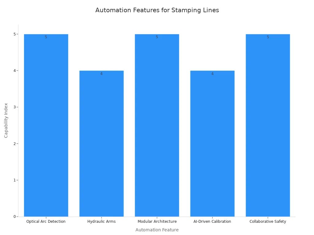
JINZHIDE exemplifies this integration philosophy, providing end-to-end support from pre-sales consultation through installation and training, including complete servo feeder press line automation from coil to finished part. This comprehensive approach ensures smooth line integration and minimal downtime during commissioning.
Choosing a Reliable Servo Feeder Supplier
Selecting a servo feeder supplier requires more than comparing price lists. The right partner delivers consistent machine performance, responsive support, and long-term reliability; the wrong choice leads to production delays, quality issues, and hidden costs. Evaluate suppliers against objective criteria.
Evaluating Experience and Manufacturing Quality
Manufacturing capability forms the foundation of reliability. A supplier with in-house production controls quality over critical components; ISO9001 certification confirms the quality management system meets international standards. JINZHIDE operates from a 5,300 m² facility in Changzhou with complete design and assembly capabilities, and has delivered more than 10,000 machines to customers in over 60 countries across automotive, home appliance, electronics, and construction hardware applications.
Equally important is application engineering. A trustworthy supplier publishes realistic accuracy, speed, and load data, then calculates your required feeding length, speed, and torque — and proposes the right model, not the most expensive one. Use these verification questions: What feeding accuracy do you guarantee in production, not in a demo? What is the spare-parts lead time for the servo motor and encoder? Can you provide three customer references running a line similar to mine? Red flags include vague certification claims, refusal to share case studies, and multi-month spare-parts lead times.
Global Support and Custom Solutions
Global support capability determines how quickly problems get resolved. Look for local agents or service engineers in your region, clear warranty terms with defined response times, and spare parts availability that keeps a stopped line from becoming a stopped business. The best servo feeder supplier combines global reach with local presence.
Custom engineering separates true manufacturers from assemblers. Standard feeder types do not fit every application; a capable supplier tailors the machine to your material, feed length, and press configuration, and can deliver turnkey solutions integrating decoiler, straightener, servo feeder, and press into a single automated line. This integrated approach reduces installation time and guarantees system-wide performance. And because upgradable controllers allow future enhancements without replacing the hardware, the right partner also protects your investment as production needs evolve.
Selecting the right servo feeder means balancing material specifications, feed requirements, press compatibility, and future-proofing. Material width, thickness, and yield strength determine motor sizing and roll configuration. Feed length and accuracy determine part quality. Press synchronization and line architecture — standalone or 3-in-1 — determine how smoothly the line runs. And open protocols plus upgradable controllers protect your investment well beyond this decade.
The numbers consistently favor doing this exercise properly: a 1.5-percentage-point scrap reduction and faster changeovers typically repay the servo premium within 12–18 months, while a mis-specified feeder generates waste for its entire service life.
Ready to specify your line? Send JINZHIDE your coil data (width, thickness, material grade), press tonnage and SPM, and a part drawing. The application engineering team will return a free feeder sizing recommendation and stamping line layout proposal — no obligation. Reach out via jinzhidestamping.com, WhatsApp +86-18932396111, or czjinzhide@163.com.
FAQ
What feed accuracy can I expect from a modern servo feeder?
High-quality NC servo feeders hold ±0.02 mm repeatability on standard precision models; heavy-gauge high-strength lines hold ±0.2 mm at a 500 mm feed. Your real-world accuracy also depends on center-line alignment with the die entry, pass line height, and coil quality (camber and waveform).
How do I match feeder capacity to my coil specifications?
Confirm maximum width, thickness, and — critically — yield strength. Standard models cover roughly 0.1–3.2 mm thickness at widths up to 1,300 mm; heavy-duty and HSS lines extend to 6.0–9.0 mm and 2,000 mm. Remember that maximum width and maximum thickness cannot be combined freely: wider coils reduce the allowable thickness at full capacity.
Can a servo feeder handle high-strength steel?
Yes, but only when specified for it. Standard feeders assume yield strength ≤245 N/mm². For HSS, choose a dedicated high-strength coil feeding line with higher servo torque, reinforced rolls, hydraulic pressing arm, and active threading — JINZHIDE's HSS lines handle yield up to 613 N/mm² and tensile up to 980 N/mm².
Standalone servo feeder or 3-in-1 compact line — which should I choose?
A 2-in-1 plus standalone servo feeder occupies ~7 m and can take ~30 minutes for setup, but offers flexibility for unusual materials and retrofits. A 3-in-1 unit needs only ~3 m, threads material in one pass, and cuts setup to ~8 minutes — usually the better choice for new lines, tight floor space, or frequent job changes.
What is the payback period for upgrading to a servo feeder?
Most facilities recover the price premium over pneumatic feeders within 12–18 months, driven by scrap reduction (from 2–3% down to 0.5–1% on tight-tolerance jobs), faster changeovers (2–5 min vs. 10–15 min), and labor savings. Evaluate total cost of ownership, not purchase price.
Can my existing press integrate with a new servo feeder?
In most cases, yes. Modern servo feeders synchronize with the press stroke using priority modes (feed-before-press or press-before-feed) and synchronous checking. Before purchase, verify that your press control system supports the feeder's signal and communication format.
What automation features should I prioritize?
Prioritize open communication protocols (Modbus TCP, EtherCAT, OPC UA) for PLC/MES connectivity, upgradable controllers that accept new software without hardware replacement, and torque-based predictive maintenance that flags roll wear or bearing issues before unplanned stops.
How do I evaluate a servo feeder supplier before purchasing?
Look for ISO9001 certification and in-house manufacturing, ask for production accuracy guarantees and customer references running similar applications, and verify spare-parts lead times for the servo motor and encoder. A supplier with real application engineering will calculate your feed length, speed, and torque — then propose the right model.
This FAQ addresses common concerns during servo feeder selection. Use these answers as a practical checklist when comparing equipment options, and request documented test data for any performance claim.