




Fix Decoiler Alignment: Diagnose & Stop Coil Tracking Errors
 Sep 14, 2026|
 View:100
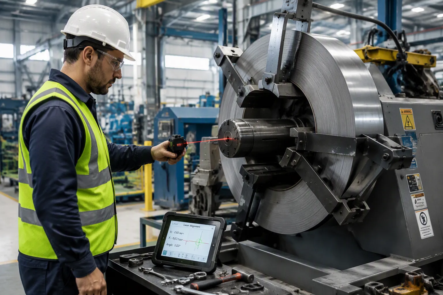
A high-speed stamping line suddenly stops under full load. Coil edges show visible damage from severe misalignment. Vibration spreads through the decoiler, rattling nearby equipment. This misalignment causes costly unscheduled downtime. Even a robust automation system requires correct alignment for reliable performance. This guide provides a systematic diagnostic framework for technicians. It covers symptoms, root causes, and modern diagnostic methods such as laser alignment. Modern diagnostic methods range from advanced laser shaft analysis to traditional visual checks and dial indicators. It explains how to fix decoiler misalignment step by step, without major component replacement. Early detection improves coil quality and extends machine life. Alignment drift often starts with foundation settling or component wear.
Key Takeaways
Watch for vibration, noise, and uneven unwinding as early signs of decoiler misalignment.
Check foundation settling, worn bearings, and hydraulic leaks as common root causes.
Use laser alignment, dial indicators, and vibration analysis for accurate diagnosis.
Correct deviations with shimming, anchor tightening, and guide adjustments.
Schedule monthly checks and lubrication to prevent drift and maximize stamping line efficiency.
Common misalignment signs in decoilers
Vibration, noise, and uneven unwinding
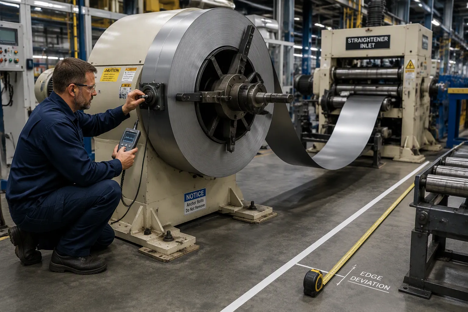
Operators often notice vibration or screeching from bearings first. These sounds signal that the decoiler spindle no longer runs true. A rhythmic thumping during unwinding points to a bent mandrel or worn bearing races. Uneven unwinding follows the same pattern. The coil pays off in surges rather than a steady stream. Tension at the straightener inlet rises and falls with each revolution. This fluctuation stresses the material and the feed rolls alike.
Vibration rarely stays contained. It travels through the base into nearby equipment. Loosened anchor bolts amplify the problem over time. A decoiler with this type of misalignment will show accelerated wear on spindles, bearings, and guide rollers. Product quality drops as surface marks and edge damage appear. These early warnings give technicians a chance to act before a major failure. Condition monitoring tools, such as a simple vibration meter, can confirm the source quickly.
Coil tracking errors and camber problems
Coil camber ranks among the most frequent symptoms of uneven rolling. The strip curves to one side as it leaves the mandrel. This curvature pushes the material against one edge of the entrance guide. Tracking errors then compound the damage. Visual inspection using a straight reference line quickly reveals the deviation. The table below shows typical camber measurement standards for steel coils.
Aspect | Standard |
|---|---|
Measurement method | Lay a fixed length (1 meter) of strip on a flat surface and measure the edge deviation from a straight reference line. |
Tolerable camber | Deviation under 2 mm over a one-meter sample is acceptable for most dies with reasonable guide clearance. |
Material Sensitivity | High-strength steel and aluminum alloys are highly sensitive to camber and require tighter tolerances (<1 mm/m) compared to standard SPCC cold-rolled steel. |
Precision requirement | Tight-tolerance dies and high-speed lines demand effectively zero camber over one meter. |
Camber severity directly reduces dimensional accuracy in roll forming. When flatness deviation exceeds 5 mm over 1 m, a multi-roll corrective leveler becomes necessary. Feeding length drift from tracking errors contributes 30-40% of scrap in typical stamping operations. In a progressive die running at 200 SPM, a feed drift of just 0.1 mm on a 100 mm feed length misaligns pilot holes with the die. At 200 parts per minute, that error converts to roughly 12,000 potentially defective parts per hour. A die smash also destroys the tool itself.
The people who run the line every day see the early warning signs: the small change in sound, the slightly rough part edge, the tiny variation in coil tracking.
These signs of mechanical deviation reduce product quality and accelerate wear. Technicians who recognize tracking errors early prevent small faults from becoming major failures. Any decoiler alignment issues traced to camber or tracking deserve immediate attention. The next step involves finding the root causes behind these patterns.
Root causes of decoiler alignment issues
Foundation settling and installation errors
A weak foundation creates the most persistent stamping line stability issues. Concrete pads settle unevenly under heavy vibration. Loose anchor bolts then allow the base to shift. Incorrect base mounting adds twist to the frame. These faults develop slowly over months of production.
Proper installation prevents most of these problems. The foundation should be leveled to a maximum deviation of 0.1 mm per meter. Technicians verify this tolerance with a precision spirit level rated at 0.02 mm per meter. A laser line or optical level checks both longitudinal and transverse straightness. Shims placed under the base plates bring the frame to this tolerance. A diagonal measurement confirms the alignment and prevents twist. This step protects against long-term misalignment.
Component wear, hydraulic system faults, and thermal expansion
Worn spindle bearings rank among the most common misalignment sources. A bearing with play lets the mandrel drift from its true center. Belt tension problems and electrical control faults also disturb rotation. Hydraulic system leaks reduce clamping force on the coil. The mandrel then slips under load. Temperature fluctuations change the frame dimensions. A cold morning start can shift shaft alignment by a measurable amount.
These types of misalignment rarely appear alone. A leaking hydraulic unit overheats nearby components. Heat then accelerates bearing wear. The resulting misalignment feeds back into the system. Tension at the straightener inlet becomes erratic. Every cycle adds stress to the coil and the feed rolls.
JINZHIDE decoilers are engineered with heavy-duty welded frames and precision-machined mandrels to resist structural deflection. Regular checks remain essential regardless of build quality. A monthly inspection catches wear before it becomes a failure. Technicians should record baseline readings for every critical measurement.
Diagnostic techniques for decoiler misalignment
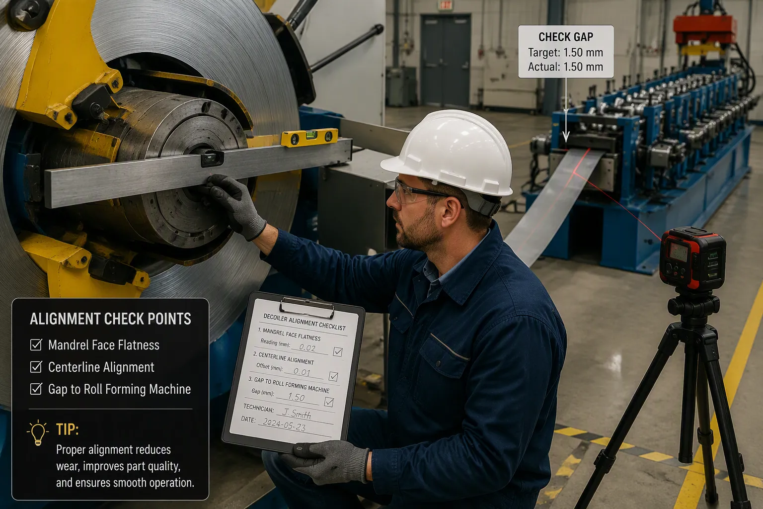
Coil Feeding Alignment Troubleshooting: Visual and Manual Checks
A systematic diagnostic approach starts with the simplest checks. Technicians should first verify the physical distance and tension control zones between the decoiler and the subsequent leveling equipment. This gap directly affects how well the coil maintains tension before entering the tooling. The table below shows the recommended spacing standards for stamping lines.
Recommendation | Ideal Standard | Purpose |
|---|---|---|
Looping Pit Depth Allocation | 1.5m to 3.0m (depending on material thickness and SPM) | Maintains constant tension and prevents material stress during intermittent feeding. |
Distance to Straightener | Optimized for material threading and initial camber correction | Allows sufficient space for edge guides to stabilize the strip before entering the leveling rolls. |
On a dedicated coil feeding line, the space between the decoiler and the straightener also sets the working range of the loop control. A gap that is too short forces the loop sensor to react faster than the drive can respond, and the resulting tension spikes look like alignment faults even when the frame is level. Measure the actual gap against the table above before adjusting any hardware.
A low-speed test feed comes next. Run the decoiler at reduced speed and watch the coil as it unwinds. The strip should pay off in a steady stream. Any surge or hesitation points to tension fluctuations or tracking deviations worth pursuing further. Watch the entrance guide as well. The strip should pass through its center without touching either side. Contact on one edge signals a tracking problem. This simple observation helps detect mechanical deviations before it damages the coil or the guide rollers.
Manual checks with a straightedge reveal camber and twist. Place a precision level across the mandrel face. A gap under the level indicates the frame has shifted. Check the anchor bolts for tightness. Loose bolts allow the base to move during operation. These visual and manual checks form the foundation of any diagnostic routine. They require no special tools and take only minutes to complete.
Laser alignment, dial indicators, and vibration analysis
Modern tools take condition monitoring to a higher level. A laser alignment system projects a precise beam along the intended centerline. Technicians compare the actual shaft position against this reference. The system calculates both angular and parallel offset. This precision alignment method works well for shaft alignment on decoilers with long spindles. Laser shaft analysis also captures data during rotation. The readings show how the shaft moves under load.
Dial indicators offer a traditional alternative. Mount the indicator on a fixed base and rotate the shaft slowly. The needle movement reveals runout and eccentricity. A dial indicator can also check coupling alignment between the decoiler and the straightener. Vibration analysis completes the diagnostic toolkit. A vibration meter or analyzer detects the frequency signature of a worn bearing. Each bearing fault produces a characteristic frequency. Technicians compare measured values against baseline readings. A rise in vibration amplitude signals developing misalignment.
A disciplined diagnostic routine catches stamping press operations disruptions before they cascade into scrap, tool damage, or unplanned downtime.
These tools help detect alignment drift with far greater accuracy than visual inspection alone. A laser system can resolve alignment errors that a straightedge would miss. Vibration analysis identifies problems before they become audible. Together, these methods give technicians a complete picture of decoiler health. The next step involves applying targeted corrections based on the diagnostic findings.
How to Fix Decoiler Misalignment: Step-by-Step Corrections
Base shimming, foundation leveling, and anchor tightening
Base shimming and foundation leveling solve many automotive stamping lines alignment issues at the source. A soft foot occurs when one corner of the base sits higher than the others. The frame then twists under load. Technicians place a dial indicator on each foot in turn. They loosen one anchor bolt at a time and watch for movement. A reading above the acceptable limit confirms the soft foot. Thin shims placed under the low corner restore full contact. The shim stack should use stainless steel sheets for durability. After shimming, tighten all anchor bolts in a diagonal pattern. This sequence prevents the base from warping during the final torque. Recheck the frame level with a precision spirit level. The goal is a flat mounting surface with no gaps under any foot.
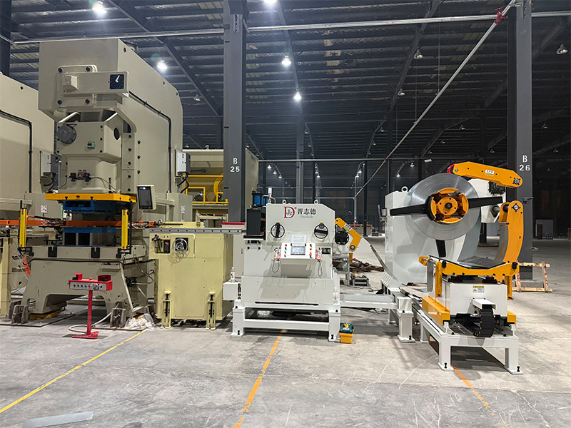
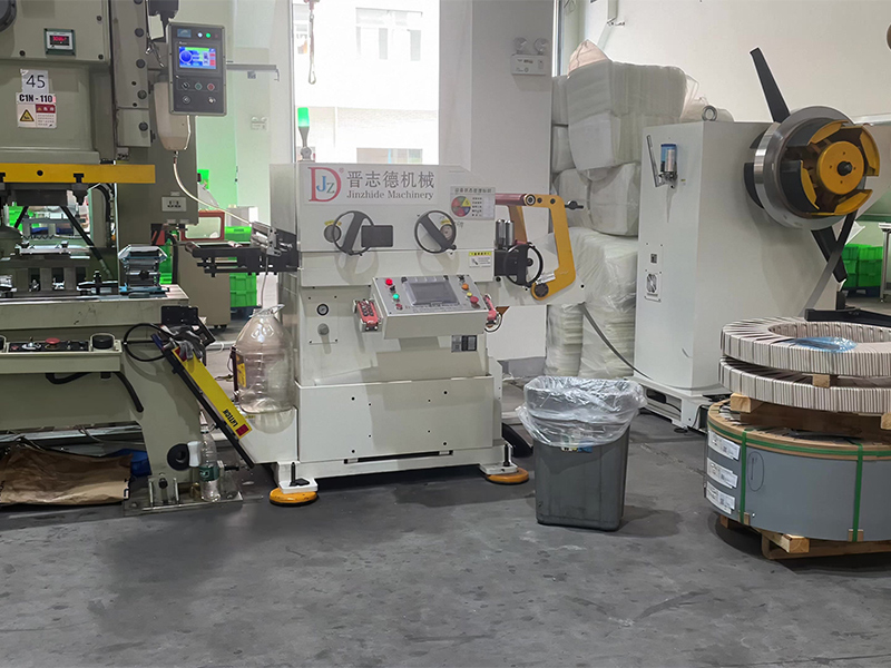
The same sequence applies to a decoiler straightener feeder, although the integrated frame is more rigid and therefore shows less warning before a soft foot transfers load into the leveling section. Check the frame level on the integrated machines first, then confirm the strip path through the straightening and feeding sections.
Guiding devices, trimming for camber, and hydraulic system adjustments
Slight camber responds well to a guiding device or a trimming process. A guiding device mounts at the decoiler exit and steers the strip back to center. This correction works best when the camber deviation stays small. For more severe camber, a trimming process removes the curved edge before the strip enters the tooling. Both remedies reduce waste and protect the dies.
Rotation problems require a different approach. Worn spindle bearings let the mandrel drift, so technicians should inspect them for play. Belt tension needs checking as well. A loose belt causes speed fluctuations that mimic misalignment. Electrical controls also deserve a review. A faulty drive signal can produce uneven rotation that looks like a mechanical fault.
Hydraulic decoilers need special attention. Inspect the system for leaks around fittings and seals. A leaking cylinder reduces clamping force, and the coil then slips during unwinding. Adjust the decoiler tension settings after any repair. Proper tension adjustment keeps the strip taut without stretching it. A pressure gauge confirms the setting matches the material specification.
Complex realignments sometimes exceed in-house capability. JINZHIDE technical support and training are available for these situations. Their engineers can perform laser shaft analysis and guide a full correction. This resource proves valuable when shaft alignment errors persist after standard fixes.
A methodical correction sequence saves hours of trial and error. Fix the foundation first, then address the strip path, and finish with the hydraulic and drive systems.
Each step builds on the last. A level base supports accurate guiding. Correct guiding reduces stress on the hydraulic unit. This order prevents a technician from chasing symptoms that return after each repair. The final step locks in the repair with a verification run at production speed, which is also the point where a technician can confirm that the fix decoiler misalignment work actually held.
Preventive maintenance for sustained decoiler alignment
Scheduled rechecks, thermal compensation, and baseline measurements
A disciplined preventive maintenance schedule protects every decoiler from gradual drift. Technicians should record baseline readings for frame level, mandrel runout, and shaft alignment during initial installation. These reference values become the standard for all future comparisons. Monthly rechecks with a precision level and dial indicator reveal small changes before they grow into serious misalignment. Seasonal temperature swings also affect frame geometry. A cold morning start can shift alignment by a measurable amount. Technicians should perform a warm-up cycle before production and recheck critical measurements once the machine reaches operating temperature. This thermal compensation step prevents cold-start misalignment from damaging the coil during the first hour of operation.
Baseline measurements also support trend analysis. A slow rise in vibration amplitude signals developing misalignment long before an operator hears unusual noise. Documenting each reading creates a history that reveals wear patterns. When a reading exceeds the baseline by a set threshold, the technician schedules a correction before the next production run. This proactive approach reduces scrap and extends component life. A preventive maintenance program built on regular rechecks catches mechanical deviations at their earliest stage.
Hydraulic system care, bearing health, and lubrication programs
Hydraulic system care prevents many alignment problems in hydraulic decoilers. Inspect fittings and seals for leaks during every scheduled service. A leaking cylinder reduces clamping force, and the coil then slips under load. Check the tension settings after any repair with a pressure gauge. Proper tension adjustment keeps the strip taut without stretching it. Replace hydraulic fluid at the manufacturer's recommended interval to maintain consistent performance.
Bearing health depends on a disciplined lubrication program. The table below shows the recommended lubricant type and frequency for spindle bearings.
Component | Lubricant Type | Frequency |
|---|---|---|
Spindle Bearings | High-grade Grease | Monthly |
Worn spindle bearings let the mandrel drift from its true center, which creates misalignment throughout the feed path. Technicians should inspect bearings for play during every monthly lubrication service. A bearing with excessive play requires replacement before it damages the shaft. Belt tension also deserves a check during these visits. A loose belt causes speed fluctuations that mimic misalignment. Combining lubrication, bearing inspection, and hydraulic care into one preventive maintenance routine keeps the decoiler running true.
Decoiler alignment is not a one-time setup, but a continuous pillar of stamping line efficiency. Left unchecked, minor deviations in the spindle or frame will cascade into severe camber, die damage, and costly unplanned downtime. By implementing a disciplined diagnostic routine—combining daily visual checks with monthly laser and vibration analysis—facilities can protect their tooling and maximize OEE (Overall Equipment Effectiveness). For complex foundation shifts or persistent tracking errors, partnering with JINZHIDE’s technical team ensures your automation line operates at peak precision in 2026 and beyond.
FAQ
How often should I check decoiler alignment?
Monthly checks work well for most production lines. Record baseline readings during installation. Compare each new measurement against that baseline. A rise in vibration or a small level change signals developing misalignment. Increase frequency after any foundation work or component replacement.
What causes common misalignment in a decoiler?
Foundation settling, loose anchor bolts, and worn spindle bearings top the list. Hydraulic leaks reduce clamping force. Temperature swings shift frame geometry. Each cause produces a distinct symptom. Vibration points to bearings. Camber points to the strip path. Tracking errors point to the entrance guide.
Can I fix misalignment without replacing major parts?
Yes, most cases respond to shimming, anchor tightening, and guide adjustment. Foundation leveling solves many base problems. A guiding device handles slight camber. Bearing replacement becomes necessary only when play exceeds acceptable limits. Complex realignments may need laser shaft analysis from a specialist.
What tools do I need for alignment diagnostics?
A precision spirit level, dial indicator, and vibration meter cover most checks. A laser alignment system adds angular and parallel offset measurement. A straightedge reveals camber and twist. These tools detect misalignment before it damages the coil or tooling.
How do I stop coil tracking problems in a stamping line?
Start with the entrance guide. The strip should pass through its center without touching either edge. Then confirm frame level and anchor tightness, because a shifted base pushes the strip to one side. Finally, check the gap between the decoiler and the straightener against the spacing table above. Most tracking errors trace back to one of these three points, and correcting them stops the drift without replacing major parts.
When should I call JINZHIDE for support?
Contact JINZHIDE when standard corrections fail to hold. Persistent shaft alignment errors, repeated bearing failures, or hydraulic faults beyond routine repair all warrant expert help. Their engineers perform laser shaft analysis and provide training. This support ensures the decoiler returns to peak performance.
Recent News
1.Punch Press Automatic Feeder: Comparing New Machines and Used Units
2026-07-172.Punch Press Auto-Feeding Upgrade: 5 Practical Setup Options
2026-07-173.Three Layouts for Decoiler Straightener Feeder
2026-09-094.Decoiler Machine Guide: Load, Width and Coil Size
2026-08-175.How to Choose a Metal Coil Feeder for Your Production Line
2026-08-24