




How Coil-Fed Stamping Works: From Metal Coil to Finished Part
 Nov 03, 2026|
 View:34
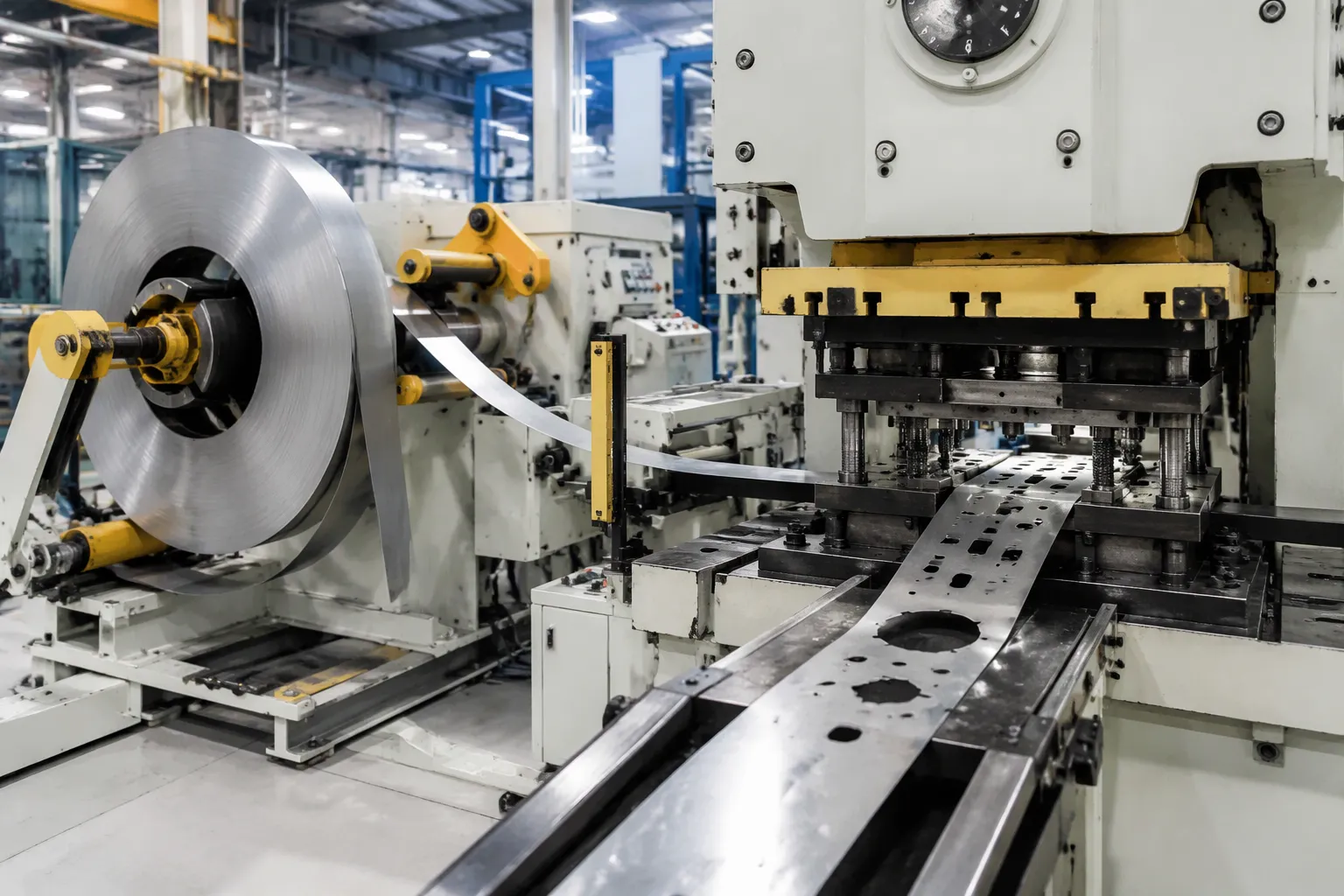
Coil-fed stamping is a manufacturing method that converts a continuous metal coil into finished parts at high volume and high speed. A decoiler releases the strip, a straightener flattens it, a feeder indexes it into a press, and a die cuts and forms each part. This article explains how coil-fed stamping works by following the process in physical order: coil loading, decoiling, straightening, feeding, stamping, and post-stamping. Each stage stabilizes the material before the next one acts on it. JINZHIDE, an ISO 9001 certified manufacturer based in Changzhou, China, builds decoilers, straighteners, feeders, and presses as one matched line.
Key Takeaways
Coil-fed stamping turns a continuous metal coil into finished parts quickly and consistently.
Each stage—decoiling, straightening, feeding, stamping, and finishing—prepares the material for the next step.
The straightener removes coil set to keep the strip flat and stable for accurate feeding.
The feeder moves the strip exactly one die station per press stroke; any mismatch causes defects.
Final inspection catches problems early and ensures every part meets the specification.
How Coil-Fed Stamping Works: Process Overview
What Coil-Fed Stamping Is
Coil-fed stamping is a manufacturing process that feeds a continuous coil of sheet metal—steel, stainless steel, aluminum, or brass—through a press and progressive die to produce finished parts. The coil is loaded and restrained, unwound under controlled tension, straightened to reduce coil set, advanced by the feeder at the die pitch, lubricated when required, then blanked, pierced, bent, formed, or drawn in the press and die. Finished parts and the remaining carrier, strip skeleton, trim, or slugs are discharged separately.
The purpose of this method is high-volume, high-speed production with consistent part quality. Stable production depends on the interfaces among material, decoiler, straightener, feeder, loop control, lubrication, press, die, and scrap system—not on the press alone. Each component must work in concert with the others to maintain the rhythm of the line.
The Equipment Line at a Glance
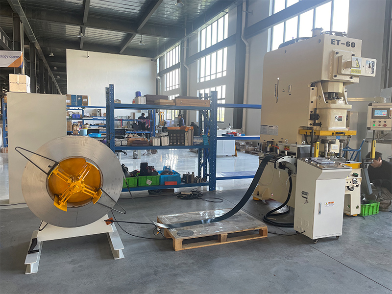
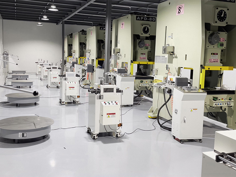
A complete coil-fed stamping line arranges its main equipment in a fixed sequence. The decoiler supports the coil and pays off strip at a controlled rate without uncontrolled overrun or excessive tension. The straightener or leveler applies alternating bends to reduce coil set and improve strip condition before feeding. A buffer—often a loop—isolates intermittent press demand from the rotating coil mass. The servo feeder advances the programmed pitch and presents the strip to the die within the available press-cycle window. The press and die then perform the cutting and forming operations.
Integrated lines may add robotic automation for part handling or transfer between stations. For high-strength steel or space-constrained facilities, 3-in-1 compact coil feed lines combine decoiling, straightening, and servo feeding into a single, synchronized unit, eliminating the need for loop pits and significantly improving feeding accuracy. Guidance, lubrication, sensing, die protection, and safety devices support the process as required. This equipment chain defines how coil-fed stamping works as a connected flow rather than a set of isolated machines.
From Coil to Strip: Decoiling and Straightening
Loading and Decoiling the Coil
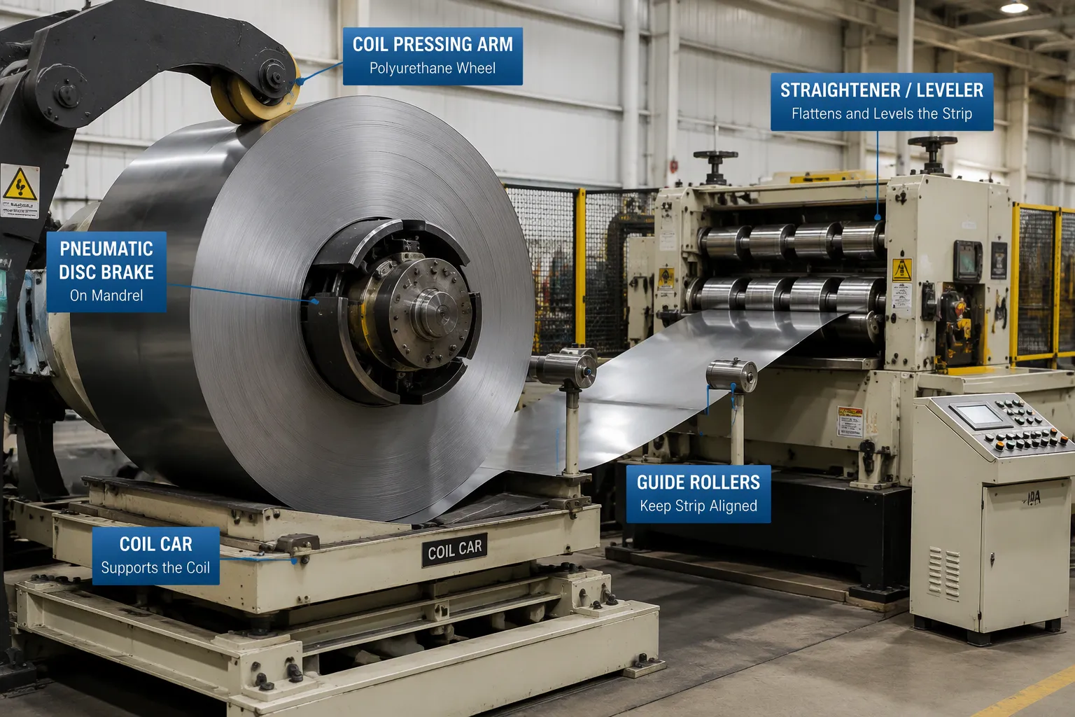
Coil loading begins with material verification. The operator confirms the grade, thickness, and width against the work order before the coil leaves the floor. A coil car then lifts the coil to the uncoiler spindle. Industry standards dictate that the car uses a wear-resisting surface and four baffle arms to prevent coil tilting, with limit switches that stop offside travel. Centering relies on visual alignment against scales on the machine body.
Once mounted, the coil is threaded into the line. A typical sequence follows:
Confirm LockOut/TagOut awareness before any intervention.
Remove leftover strip or butt-weld the new coil to the old stock.
Load the stock reel, cradle, and straightener.
Load stock into the feed.
Walk or inch the strip through the die using jog control.
During uncoiling, a coil pressing arm with a polyurethane wheel holds pressure on the coil to prevent strip loss. A pneumatic disc brake on the mandrel allows precise braking, and two non-motorized guide rollers keep the strip tracking within the coil width.
Straightening for Flat, Stable Strip
Every coil carries coil set—the memory of its wound shape. Metallurgical experts describe coil set as the steel remembering that it was in coil until a straightener resets that memory. If the straightener lacks power or is set improperly, coil set remains and the strip may arch before the feeder.
Straightening applies alternating bends that remove coil set and crossbow before the strip enters the die. This improves feed stability and pilot location, since a flat strip seats consistently against the gauging. Levelers go further: Industry publications report that levelers correct edge wave and center buckle by equalizing length and stress, reducing springback after stamping.
Setup requires judgment. A 0.5 mm soft aluminum strip, a 2.0 mm carbon steel strip, and a wider stainless coil react differently through the same roller gap, according to experienced operators. Too little pressure leaves coil set; too much over-bends the material or marks the surface. Operators test short samples and adjust gradually.
| Test strip result | Likely cause | Adjustment direction |
|---|---|---|
| Upward arc becomes downward reverse arc | Pressure too heavy | Raise adjustment slightly |
| Upward arc remains, smaller | Pressure still insufficient | Lower handwheel gradually |
| Strip deviates left or right | Unequal side pressure | Balance handwheels, check guides |
| Surface marks appear | Roller cleanliness or pressure | Clean rollers, reduce pressure |
Re-reeling is an additional function on many coil-fed press lines, allowing strip to be rewound for storage or transfer. When a coil reaches its end, the trailing wrap can release suddenly—a coil pop. Operators should stand clear of the payoff path and let the pressing arm and brake control the final wraps.
Feeding and Stamping the Strip
How the Feeder Moves Material
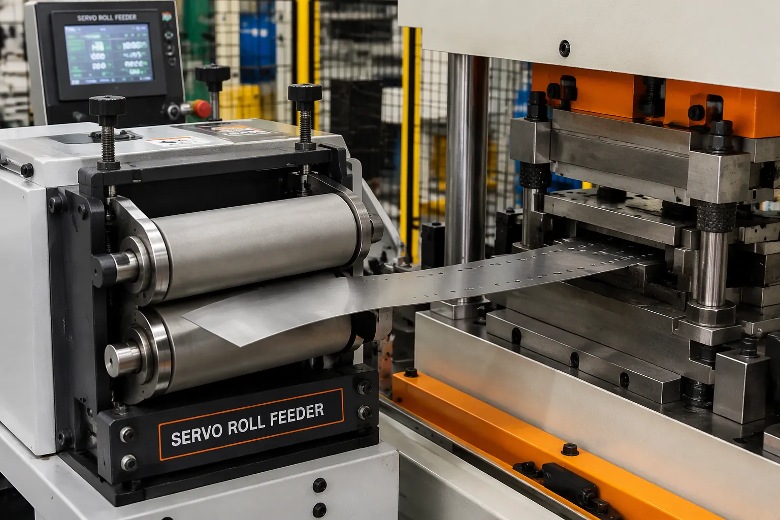
The feeder advances the strip by a preset length during each press stroke. This length is the feed pitch, and it must match the die station spacing exactly. A short pitch with frequent cycles demands fast motion response and high repeatability. A long pitch demands attention to material inertia and the acceleration and deceleration settings. Engineering guidelines note that the strip must complete its advance inside the time window the die and press allow. If press speed rises and the feeder cannot finish its movement in that window, incomplete feeding or positioning errors follow.
Feeder types establish the pitch in different ways. A servo roll feeder uses a controller to command roll rotation through a servo drive and a programmed recipe. A mechanical roller feeder derives its advance from press-linked motion and an adjustment mechanism. A grip or clamp feeder advances the strip through alternating gripping and transfer strokes. JINZHIDE's engineering data shows that servo feeders reach feeding accuracy up to plus or minus 0.15 mm. Each type has a place: mechanical feeders suit stable, repetitive work, pneumatic feeders suit pre-feeding and small batches, and servo feeders suit precision and speed.
A pneumatic feeder shows the cycle plainly. The clamp grips the material to prevent slipping. The drive moves the strip forward by the set feed stroke. The material reaches the die at the required distance. The carriage returns while the grip holds the strip against backward slip. The cycle then repeats.
Thin and thick stock call for different setups. Thin sheet work focuses on roller pressure, surface protection, and repeatability. Thick sheet work focuses on clamping capability, rigidity, and feeding resistance. Motor power alone does not prove a feeder suits thick material. Material thickness, width, type, feed length, and speed must be assessed together.
Die Operations: Cutting and Forming
A progressive die performs several operations inside one die block. Each station carries out one stage, and every press stroke moves the part one station closer to completion. Cutting stations pierce holes, notch edges, and blank outlines. Forming stations bend, draw, or coin the material into shape. Separation and trimming stations free the finished part from the carrier and remove excess stock.
The strip itself acts as the transfer mechanism. The feeder indexes the strip by one pitch, the press closes, and every station works at once. The part in the first station receives its initial cut. The part in the last station separates as a finished piece. Scrap and slugs exit through the die or fall clear of the strip path.
Setup discipline keeps this rhythm intact. Feed length must equal the station pitch. Pilot pins must locate the strip before cutting begins. Die protection sensors watch for misfeed, short feed, and slug buildup. A misfeed at one station damages every station downstream, so the sensors protect the whole die. This is where coil-fed stamping works as a single coordinated system rather than a press acting alone.
Post-Stamping: Deburring, Finishing, Inspection
Deburring and Surface Finishing
Burrs are a normal outcome of stamping. A small ridge or protrusion often passes without action. Deburring becomes necessary when a sharp edge creates a handling hazard, interferes with fit, or violates a radius or edge-break specification. The Precision Metalforming Association (PMA) notes that most deburring on stampings serves precision requirements for a radius edge or edge break, and that stamped parts needing deburring range from very small sizes up to 16X6 inches.
Common options fit different production needs:
Barrel and vibratory finishing tumble or vibrate parts in abrasive media and cleaning solution. Both suit large batches and also remove oil, rust, oxidation, and heat-treatment scale.
Electropolishing removes surface metal for micro-deburring of very small or complex parts. It produces a smooth, mirror-like surface, and surface finishing experts describe it as a more expensive option.
Powder coating, e-coating, plating, heat treating, and cleaning address surface protection and appearance rather than burrs alone.
Deburred parts install more easily and carry a premium finish compared with parts straight from the press.
Inspection and Quality Checks
Inspection closes the loop on the whole process chain. Checks begin at first-off approval after die setup and continue through in-process patrols and final inspection. Quality control frameworks map each common defect to its best control point. Wrong grade or thickness traces to incoming inspection and mill certificate review. Hole misposition and bad flange angle trace to first article inspection. Growing burrs and drifting dimensions trace to die wear, caught by in-process patrol checks and SPC. Scratches and coating flaws trace to handling and finishing, caught at final inspection with visual standards.
Final checks verify dimensions, appearance, labeling, and packaging against the drawing and specification. Records, batch identification, and AQL sampling confirm the delivered condition. This feedback protects every earlier stage, from coil loading through stamping, and keeps finished-part quality consistent.
Coil-Fed Stamping Works as one connected flow. A coil is loaded and verified, decoiled under controlled tension, straightened to remove coil set, fed at the die pitch, stamped through progressive stations, then deburred and inspected. Each stage stabilizes the material for the next, and no stage compensates for a weak predecessor.
Use this checklist to verify setup at each stage:
Coil grade, thickness, and width match the work order.
Straightener removes coil set without marking the strip.
Feed pitch equals the die station spacing.
Die protection sensors respond to misfeed.
Final inspection records match the drawing.
Consistent finished-part quality depends on every stage holding its setting through the run.
FAQ
What materials can run through a coil-fed stamping line?
Common materials include carbon steel, stainless steel, aluminum, and brass. Each grade behaves differently through the straightener and feeder. Operators verify grade, thickness, and width against the work order before loading. Setup settings then follow the material rather than a fixed recipe.
Why does feed pitch matter so much?
Feed pitch must equal the die station spacing exactly. A mismatch shifts every part in the progressive die by the same error. Short feeds leave incomplete cuts. Long feeds distort pilot location. Die protection sensors catch the resulting misfeed before downstream stations take damage.
Which feeder type suits which job?
| Feeder type | Typical fit |
|---|---|
| Servo roll | Precision and speed, recipe-driven pitch |
| Mechanical roller | Stable, repetitive work |
| Gripper or clamp | Alternating grip and transfer strokes |
| Pneumatic | Pre-feeding and small batches |
The choice follows material thickness, width, feed length, and press speed together, not motor power alone.
When is deburring actually required?
Deburring becomes necessary when a sharp edge creates a handling hazard, interferes with fit, or violates an edge-break specification. Many stampings need no action beyond a light edge break. Barrel finishing, vibratory finishing, and electropolishing each fit different part sizes and batch volumes.
How is finished-part quality verified?
Checks start at first-off approval after die setup. In-process patrols watch for growing burrs and drifting dimensions from die wear. Final inspection confirms dimensions, appearance, labeling, and packaging against the drawing. Records and sampling then confirm the delivered condition.
Optimize Your Stamping Line Today
Looking for a reliable decoiler, straightener, or a complete 3-in-1 coil feed line? Contact JINZHIDE's engineering team for a free consultation and custom line design.
Get a Free Quote & Line Design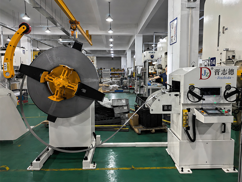
Recent News
1.Decoiler Machine Guide: Load, Width and Coil Size
2026-08-172.Fix Decoiler Alignment: Diagnose & Stop Coil Tracking Errors
2026-09-143.3 Decoiler Straightener Feeders Installed in Malaysia
2026-09-204.How to Reduce Material Scrap in Coil-Fed Stamping Production
2026-10-135.4 Light Duty Decoiler Straightener Feeders Installed
2026-09-29