




How to Reduce Material Scrap in Coil-Fed Stamping Production
 Oct 13, 2026|
 View:70
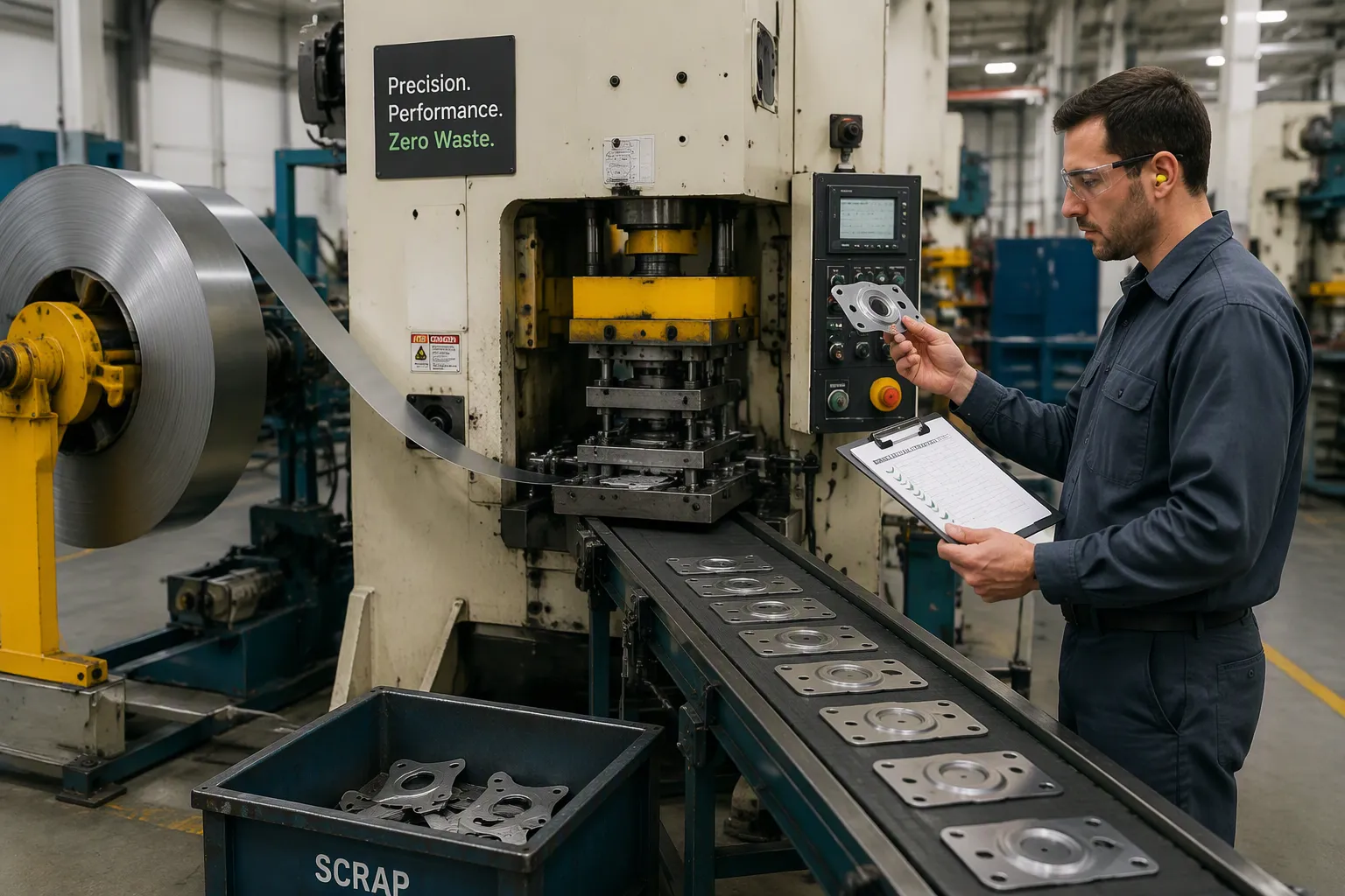
High-volume coil-fed stamping quietly erodes margins through material waste. A 2% scrap rate across a million-part run wastes the steel, press time, and labor behind 20,000 parts that never ship. A supplier quoting a lower piece price but running higher waste can still lose to a cleaner operation on total cost per good part. How does a plant reduce material scrap? Name every waste stream first, then work the three biggest levers in order: strip layout and coil planning, die and lubrication condition, and feeding accuracy. Weekly scrap data holds all three in place, and together they push a progressive stamping line well below the 2–3% that most plants accept.
Key Takeaways
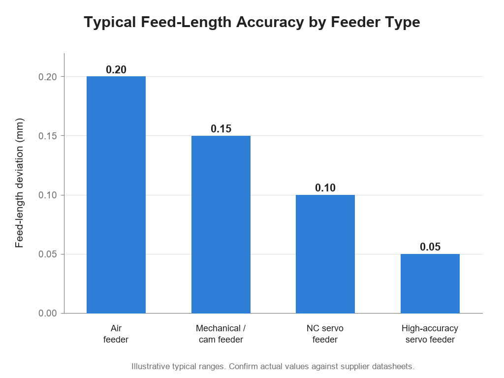
Feed-length variation is the largest controllable waste source in coil-fed stamping, and a servo feeder holding ±0.05 mm feed-length accuracy removes most of it.
Strip layout and die condition set the ceiling on material utilization. Validate both on a pilot run before you freeze coil width.
Feeding accuracy protects tooling as well as material. One bad advance can damage a die that costs more than a year of scrap.
Measure scrap weekly by root cause. A Pareto chart shows which of the six common causes to fix first.
Set a realistic target: below 3% scrap on a well-run line, below 1% for best-in-class, and treat 5% as an alarm.
What Material Scrap Really Costs
Scrap is not an abstraction. It is purchased coil that never becomes a sellable part, plus the press time and labor spent making it. The number that decides whether a job is profitable is cost per good part:
Cost per good part = (material + labor + machine time + tooling) ÷ good parts shipped
Scrap pushes both sides of that fraction the wrong way. It consumes material that was already paid for, and it spreads fixed press time across fewer sellable parts. Two plants running the same 1,000,000-part order, both consuming 0.45 kg of coil per part produced and running at 60 strokes per minute, show the gap:
Item | Line A — 2% scrap | Line B — 5% scrap |
|---|---|---|
Parts that must be produced | 1,020,408 | 1,052,632 |
Coil consumed | 459,184 kg | 473,684 kg |
Extra coil purchased | — | 14,500 kg (+3.2%) |
Extra press time | — | About 9 hours |
Additional parts to scrap, sort, and bale | — | 32,224 |
Because scrap still has resale value, the material penalty is not the full coil price. It is the spread between what you pay for coil and what a scrap dealer pays you, plus the machine time and labor that produced nothing sellable. That is why two quotations built on different scrap assumptions rarely compare as cleanly as the piece price suggests.
Sources of Waste in a Coil-Fed Stamping Line
Trim Losses, Skeletons, and Coil Ends
Every coil-fed stamping line generates several predictable waste streams. Trim scrap comes from the outer edges of the strip. The skeleton is the remaining web after blanks are cut. Punched web is material removed by holes and cutouts. Coil ends are the short lengths left at the start and finish of each coil. Setup test pieces are the first parts run while the die and feeder are dialed in.
A well-run coil-fed production line typically produces 2–3% scrap, which sounds small until it is spread across a year of tonnage. The opportunity is not one mystery loss; it is the ranking inside those streams. Trim loss responds to strip layout. Skeleton waste responds to nesting. Coil ends respond to coil planning. Setup pieces respond to faster changeover and better first-part accuracy. Each cause has a different fix, so the first job is deciding which one to attack.
Setup Defects and Feed Variation
Setup defects cluster at the start of a run. Parts are made before the strip is aligned, the die is seated, and the feed length is confirmed, and every part from that window is suspect. Inaccurate feeding is the bigger and more persistent problem, and it stands out as the largest controllable source of material waste on a coil-fed line. A feed that overshoots or undershoots by even a small amount shifts the blank inside the die, producing a misaligned part, uneven trim, or a torn edge.
Feed variation also wastes material between good parts. The cause is rarely the feeder alone: strip tension, straightener settings, and loop control all interact. A loose loop lets the strip surge. A tight loop drags against the feed rolls. Both conditions shorten or lengthen the advance. The scrap produced this way is invisible in a single part but compounds across a long run.
Proven Ways to Reduce Material Scrap
To reduce material scrap effectively, tackle layout and die care first. Waste starts with the strip layout drawn in the tool room and the die condition inside the press, and those two decide how much purchased coil becomes sellable parts.
Optimize Blank Nesting and Strip Layout
Strip layout sets the theoretical limit of material utilization. Engineers rotate, mirror, or pair blanks to close the gaps between parts, and multi-part-per-stroke dies serve high-volume runs. Every decision reshapes the strip layout, which then dictates coil width and feed pitch.
Aggressive layout reduction raises utilization on paper but weakens the carrier strip. A weaker carrier raises feeding sensitivity and tooling risk. One battery contact project showed the trade-off clearly: its CAD strip layout achieved excellent theoretical utilization, yet pilot production suffered unstable progression after several forming stations. Engineers widened the carrier slightly and reordered stations. Production stabilized, indexing variation dropped, and maintenance intervals lengthened. Total cost fell because reliability improved.
A proven sequence moves from geometry to validation:
Rotate, mirror, or pair blanks to close the gaps between parts.
Pull the blank outline as close to the finished part as the forming stations allow.
Trial a narrower coil width and a shorter feed pitch, then measure the change in scrap.
Rework addendum geometry so less extra material is carried into forming.
Run a pilot lot and inspect for wrinkles, necking, and carrier instability.
Freeze the validated coil width, then buy to a tighter width tolerance.
Validate the part and the strip layout together. A layout that maximizes utilization alone will not survive production, so revisit it after the first pilot runs to capture real constraints.
Upgrade Die Care and Lubrication
Strip layout sets the ceiling for material utilization. Die condition decides whether production reaches it. Worn edges dull, clearances shift, and tolerances drift. Scheduling maintenance by stroke count keeps part quality stable between services. In-die sensors detect a mis-feed or a buckle and stop the press, avoiding the die smash that creates the largest single scrap event a line can suffer.
Lubrication consistency matters as much as tool geometry. An automatic mist or roller system applies stamping oil uniformly, while manual brushing leaves dry spots and causes galling. Optimizing die clearance by material and thickness reduces burrs, and blade clearance and alignment in shearing control roll-over. These process-side levers are central to any metal stamping automation project, because a die that runs consistently is the only reason a tight strip layout stays viable in production.
Cut Coil-End and Changeover Waste
The two waste streams most plants never attack are the coil ends and the parts made while a job is being set. Both are planning problems more than equipment problems. Order coil lengths that divide evenly into the run, and the remnant at the end of the last coil stops being a partly paid-for offcut. When a remnant is unavoidable, label it with material grade, thickness, and weight, then return it to stock as a scheduled job for a smaller part instead of letting it sit in a corner.
On the setup side, the goal is fewer strokes before the first good part. Pre-stage and pre-set the next die, use quick clamping and standard shut heights, and keep a setup sheet that records the exact feed length, loop setting, and pass line for that tool. Confirm the first advance with the feeder's own length check instead of running parts through the die. Every stroke saved here is a part that never enters the scrap bin.
Improve Feeding Accuracy in Coil-Fed Stamping
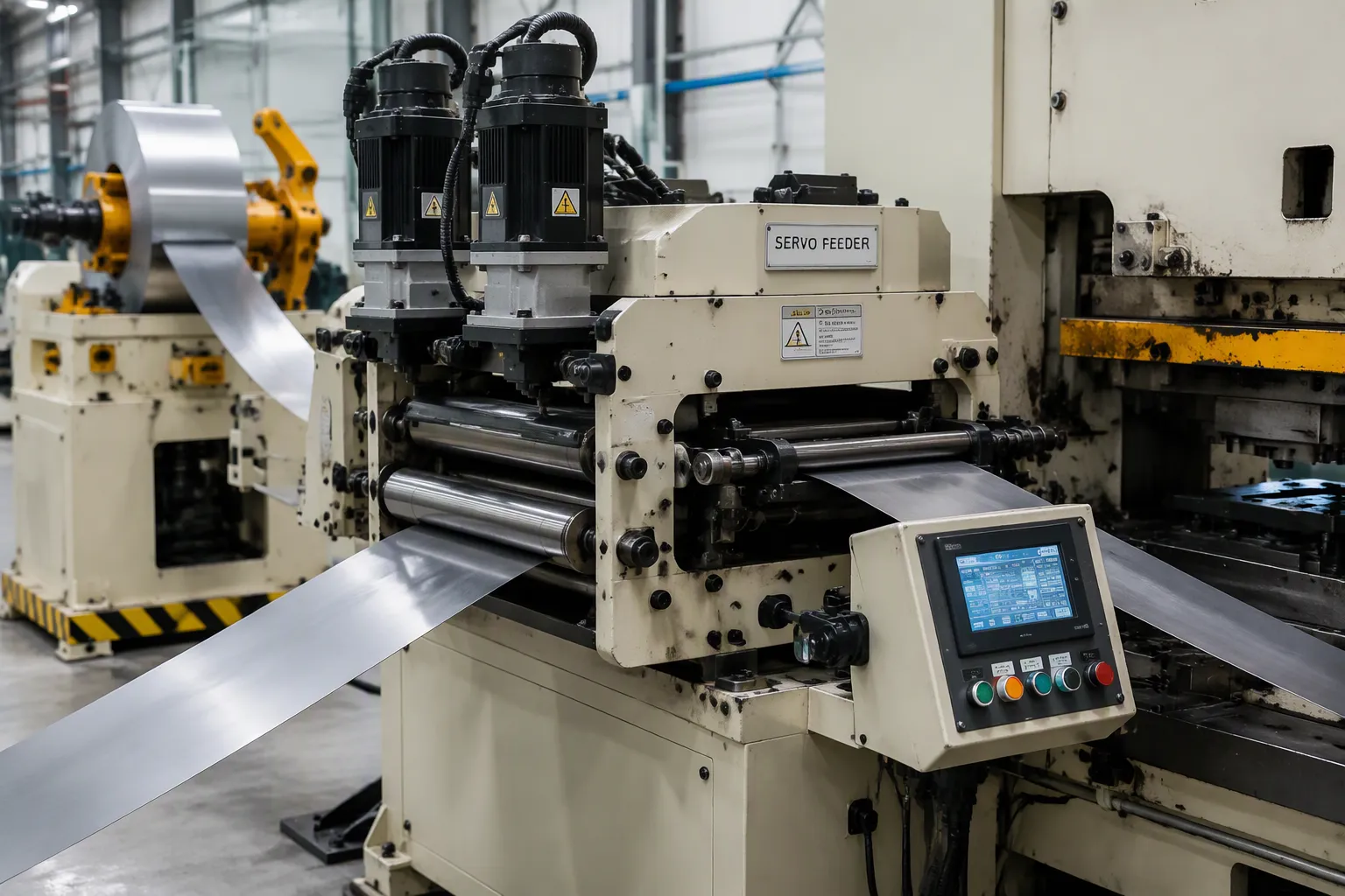
How Servo Feeder Accuracy Cuts Scrap
Feed-length variation is the largest controllable cause of material waste in any coil-fed line, and it is also the easiest to measure. A feeder specified at ±0.05 mm holds the strip inside the trim allowance that the strip layout reserved for it. A feeder that drifts 0.10–0.15 mm spends that allowance, and the next thing the die meets is a misaligned pilot. Read any accuracy figure together with its basis: per advance, per metre of feed length, or repeat accuracy under full coil load — the three are not interchangeable.
Feed-Length Issue | Effect on Stamped Part |
|---|---|
Feed length drifts between strokes | Progressive-die stations no longer line up; mis-hits, tool damage, ruined blanks |
Strip tension swings high or low | Strip shifts during punching; uneven trim edges and rejected parts |
Guide wear or late feed release | Material creeps while the punch enters; oval slots and torn edges |
Slippage or overrun on a single advance | Off-pitch cut length and misaligned pilot holes; every part from that strip length is suspect |
The cost of drift is not only the scrapped part. A strip that moves while the punch is entering can mark or crack a punch, and a mis-hit can take a die out of service for days. That is why feeding accuracy is usually the first specification to settle when you match a servo feeder to a press and a feed length, and why a slower but accurate line often out-earns a faster, looser one.
Straightening, Tension, and Alignment Controls
Coil straightening removes stress and curvature before the strip enters the die. Unstraightened coil causes misfeeds, poor positioning, jams, warped parts, die crashes, and excessive downtime. A decoiler straightener combines unwinding and leveling in one unit, and the roll count has to suit the material thickness, because too few rolls will not remove coil set no matter how the settings are trimmed. Flatness, not just straightness, is what keeps the feed repeatable.
Tension control between the decoiler and the feeder acts as a buffer against sudden demand spikes. An unstable loop either pulls against the feeder or releases too much strip, and both conditions show up as feed error. Loop controls monitor loop size and adjust decoiler speed to hold a consistent flow. When coil wanders sideways instead of surging, the fix is usually mechanical: decoiler alignment and coil tracking faults show up as uneven trim long before they show up as a stopped press.
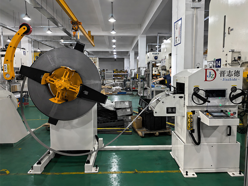
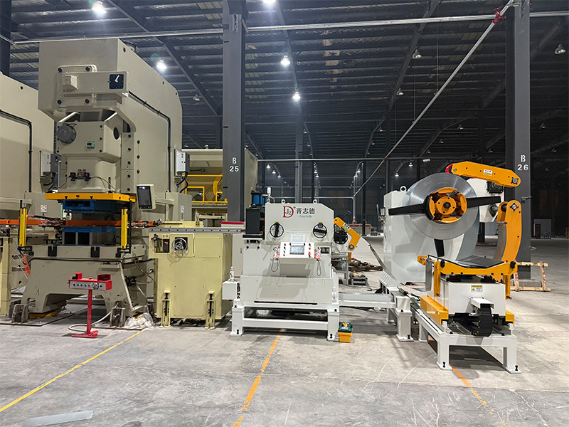
Alignment guides should control lateral position without forcing the strip off its natural path. Forced lateral guidance damages edges and makes the strip wander again as soon as it leaves the guide. A three-in-one decoiler straightener feeder, the configuration Jinzhide builds for progressive and multi-station dies, shortens the material path between unwind and press and removes the loop instability that separate units introduce. That is why an integrated line holds its accuracy more consistently than the same feeder run standalone, at a lower capital cost than three separate machines.
Build a Data-Driven Scrap Reduction Program

Track Waste Metrics and Root Causes
A scrap reduction program starts with measurement. Manufacturers separate and weigh rejected parts at each production stage, then enter the data into a Manufacturing Execution System (MES) or Quality Management System (QMS). To calculate the scrap rate, divide the weight of all scrap — offcuts, rejected parts, and setup pieces — by the total weight of coil consumed, then multiply by 100. That percentage becomes the baseline every later change is measured against.
Several metrics deserve regular attention. Setup scrap counts the parts made before the die and feeder stabilize. Defect counts track rejects by reason, such as mis-hits, burrs, or dimensional errors. Scrap cost per good part divides total defect cost by good units shipped. First pass yield shows how much of the run needed no intervention at all. Visual timelines on the shop floor show run time, unplanned downtime, and coil changes at a glance. A sudden spike on a night shift usually points to tooling, while a steady rise across all shifts more often points to material quality or feeding.
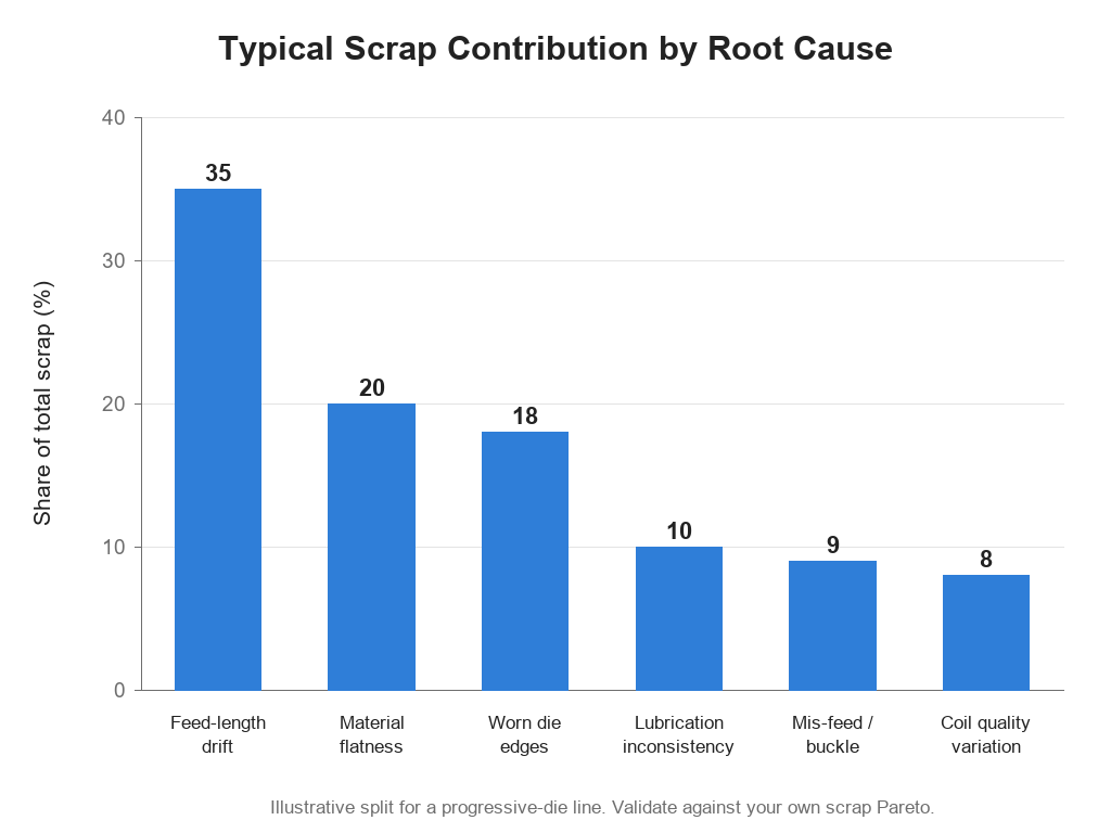
Plot the data weekly as a Pareto chart and the ranking does the prioritizing for you. The split below is typical rather than universal, so treat it as a starting point and replace it with your own numbers as soon as you have two or three months of records.
Scrap Cause | Typical Contribution | Primary Fix |
|---|---|---|
Feed length drift | 35% | |
Material flatness | 20% | Add or upgrade straightening capacity |
Worn die edges | 18% | Stroke-count maintenance |
Lubrication inconsistency | 10% | Automatic mist lubrication |
Mis-feed / buckle | 9% | In-die sensors and press stop |
8% | Incoming coil inspection |
Feed-length drift remains the largest single contributor, and it also sets up several of the smaller ones, because unstable tension and mis-feeds are usually the same problem seen from a different angle. Fix the feeding and material variables first, since drift affects every part. Then refine the die variables, change one thing at a time, and measure it for a full production day. That discipline is what keeps scrap falling instead of drifting back.
Set Targets and Sustain Improvements
Realistic targets guide progress. A well-maintained coil-fed line should hold scrap below 3% of coil material consumed, and best-in-class operations reach below 1% on stable production runs. Treat 5% as a warning threshold that triggers a review of feeding accuracy and material condition. Make the goal specific — cutting the scrap rate by a defined number of percentage points within a stated period — and treat a 30–50% relative reduction as a realistic medium-term ambition for a coordinated program.
Benchmark | Target / expectation |
|---|---|
Practical scrap rate | Below 3% of coil material consumed |
Best-in-class scrap rate | Below 1% on stable production runs |
Warning threshold | Above 5% — prioritize feeding accuracy and material condition |
Feed-length drift share | Typically 30–40% of total scrap, and the first target for corrective action |
Realistic program gain | 30–50% relative reduction once feeding, layout, and die care are fixed together |
Sustaining gains takes discipline. Standardize setup and tooling procedures so every run starts the same way. Apply preventive maintenance to dies and feeders, replacing worn components before they cause dimensional drift. Perform first article inspection before full production and monitor key dimensions during forming. Track scrap by machine, product, and shift, identify root causes such as tooling, material, or handling, and close each one with a corrective action. Precision tooling, advanced die design, and certified quality systems work together to hold a higher yield.
Integration is what keeps the numbers from eroding. The servo feeder, straightening unit, and loop control have to operate inside one synchronized process window, because at high speed a small timing error turns into a repeating mis-feed and growing burrs. The sustainable target is the highest speed at which the whole line keeps making conforming parts with acceptable die life and uptime. Improvements in feeding, straightening, and lubrication compound slowly, and weekly Pareto reviews are what stop them from slipping back.
Recover Value from the Scrap You Cannot Avoid
Zero scrap is not a realistic target, and it is not the goal. Unplanned, unmeasured scrap is. What is left over still has a market, and how it is handled decides how much of the loss comes back. Segregate by alloy from the start, because carbon steel, stainless, aluminum, and copper or brass terminals carry very different resale values, and one mixed bin drops the whole lot to mixed-scrap pricing. Keep oil-wet material separate if the dealer requires it, and bale or briquette so handling and freight do not eat the recovery.
Then close the loop: weigh scrap out weekly and reconcile it against the rate you calculated from production data. A gap between the two usually means scrap is leaving the building unrecorded, or that the reported rate only counts the parts somebody remembered to log.
Reducing waste is ongoing, not a one-time fix. Begin with one press line or a high-volume part family: measure the current scrap rate, then work layout, die care, and feeding accuracy in that order. Review servo feeder accuracy, straightening performance, and die condition first, because feed drift remains the largest controllable loss. Set a target of below 3% of material consumed, then push toward below 1% on stable runs. Review the Pareto chart weekly, refine one variable at a time, and hold each gain before moving to the next. Jinzhide builds the decoiler, straightener, and servo feeder systems that keep these numbers in place — send us your material grade, thickness, and feed length, and we will confirm the configuration for your line.
FAQ
What causes the most material waste in a coil-fed stamping line?
Feed-length drift, which typically accounts for 30–40% of total scrap. It is the largest controllable cause because a single bad advance mispositions the strip for every station downstream, so one error produces several defective features on the same part. Checking pilot-hole position against the strip edge once a shift is enough to catch it before a whole coil is affected.
How much can a servo feeder reduce scrap?
It depends on how much of your scrap comes from feed variation. If drift is behind roughly a third of a 2.5% scrap rate and an accurate feeder removes most of it, expect the rate to settle near 1.9–2.0%, a gain of about half a percentage point. When you compare feeders, check what the accuracy figure is measured against — per advance, per metre of feed length, or repeat accuracy under full coil load — because the three are not interchangeable.
What role does straightening play in scrap reduction?
Straightening removes coil set and cross-bow so the strip enters the die flat. A strip that is straight but still bowed feeds at a slight angle, which shows up as edge wave, uneven trim, and pilot holes that drift sideways rather than along the feed direction. Match the roll count and roll diameter to the material thickness; a leveler with too few rolls cannot remove the curvature no matter how it is adjusted.
What scrap rate should a well-run line achieve?
Below 3% of the coil consumed is a fair benchmark for a well-maintained line, and below 1% is achievable on stable, high-volume runs with good tooling and tight feed control. Watch the trend rather than the monthly average, because a single shift spiking above the baseline is a far more actionable signal than a slow drift nobody notices.
How does metal stamping automation support scrap reduction?
Automation closes the loop between the feeder and the press. In-die sensors stop the press on a mis-feed before the same mistake repeats for the rest of the strip, the feeder reports every advance so drift is caught in strokes rather than in final inspection, and the data ties each coil to the parts it produced. That is the practical payoff of metal stamping automation: scrap becomes a measured number instead of an estimate at the end of the month.
Recent News
1.How to Troubleshoot Coil Feeder Problems Step by Step
2026-09-282.Bull Group Reorders 6 Thin Plate Decoiler Straightener Feeders
2026-09-173.3 Decoiler Straightener Feeders Installed in Malaysia
2026-09-204.Three Layouts for Decoiler Straightener Feeder
2026-09-095.1600mm 3-in-1 Feeder Installed in Thailand
2026-09-07